LIBRARY
Comparison of Critical Conduction Mode, Triangular Conduction Mode and Fixed Frequency Modulation Schemes for Single-Phase H-Bridge Boost PFC

The structure of the H-Bridge PFC and its equivalent circuit when input voltage is positive is shown in Fig.1. The two switches of one leg operate at the mains frequency and the switches of the other leg operate at high frequency.
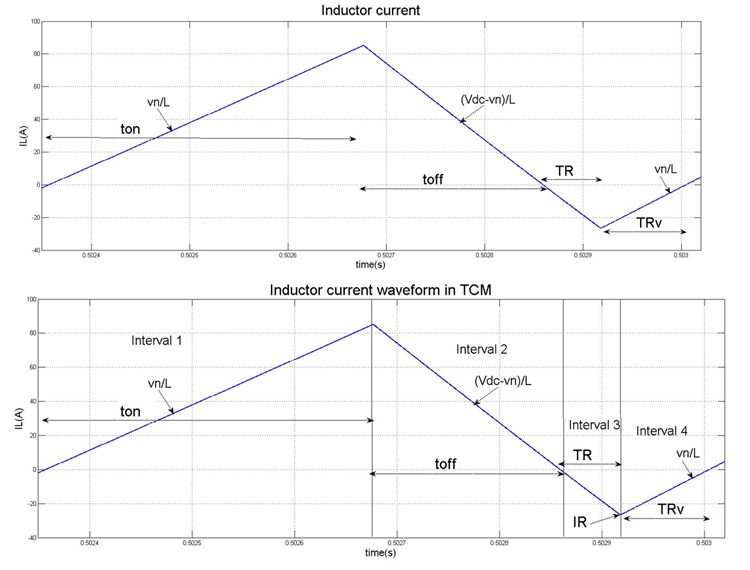
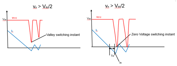
The current in the inductor is brought to zero as shown in CRM in Fig 2. However, this allows ZVS turn-on of the main switch only when vin
Thus TCM reduces the turn on losses of the main switch but it results in higher turn off losses for the auxiliary switch. Both CRM and TCM have the drawback of variable switching frequency. However, TCM can be modified to obtain a fixed-frequency PWM switching by choosing a particular duty ratio.


