


LIBRARY
Loss Minimization for Coupled Inductors with Significant Ac Flux
Year: 2015
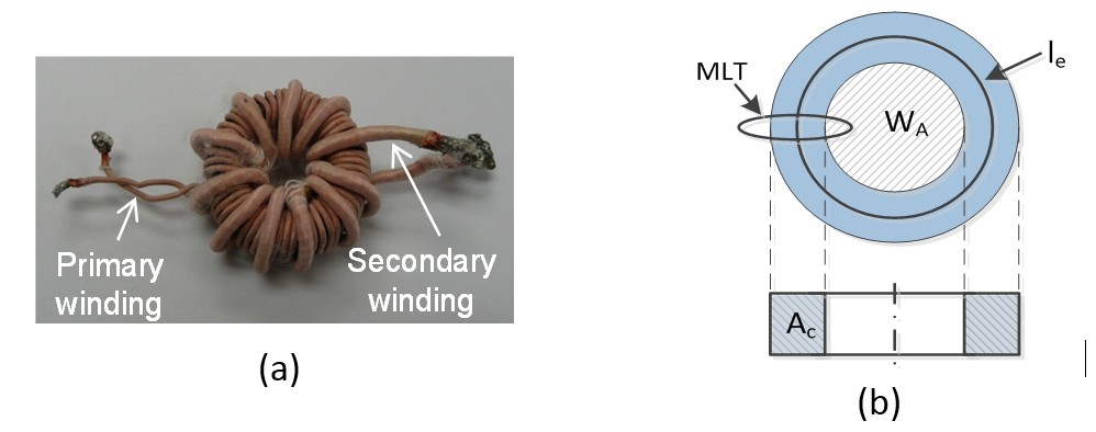
Fig1. (a) Prototype of coupled inductors and (b) definition of MLT, WA, le and Ac for toroid core used in the analysis.
The procedure of core selection is demonstrated for the coupled inductors shown in Fig. 1 (a). The definition of mean length per turn MLT, window area WA, effective length le, and effective area Ac for the toroid core used in the analysis are shown in Fig. 1 (b). The Kgac method is an extension of the Kg method. With the "Kgac" method, a designer can select the magnetic flux density based on the thermal constraint. An empirical relationship among the effective area (Ac), the mean length per turn (MLT), the window area (WA), and the volume (Ve) is suggested for the derivation of the core volume that minimizes the total loss. Under the constraints of ac flux density, inductance and window area utilization, the optimal core volume is derived by
where
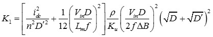
Fig. 2. shows the comparison of losses and volumes for Kgac, Ap and Kg methods based on the 30-W flyback converter at 200 kHz. If core loss is neglected in the Ap and Kg methods, the core loss density of the Ap and Kg methods are 9.3 times as high when compared to the Kgac method, which means the temperature of the core will be unacceptably high at the normal cooling condition. The measurement results are consistent with the theoretical calculations shown in Fig. 3.
