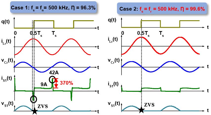
Fig. 1. Simulation waveforms of power amplifier operating at natural frequency and resonant frequency
The current-fed power amplifier (PA) is used to generate high frequency alternating current (ac) driving the antenna L
r. It consists of two filter inductors L
f, two MOSFETs, and a parallel resonant tank with high quality factor (Q). Inductor L
f emulates a constant current source and supplies power to the tank. The PWM signals of the two MOSFETs are complementary with each other and have a 50% duty ratio. The switching frequency of MOSFETs may be as high as several MHz with a several kW power rating. Thus, Zero-voltage switching (ZVS) is an important factor in decreasing the switching loss. While a large L
f could be employed to emulate a nearly ideal current source and realize ZVS when switching at natural frequency f
n, it introduces a large foot-print and decreases the power density. On the other hand, small L
f introduces a large current ripple, and if still switching at natural frequency, a large current spike will flow through the MOSFETs at switching instant increasing the conduction loss of the MOSFETs and introducing extra stress (as shown in Fig 1). The large current spike is originally caused by the phase shift between the PWM signal and the tank voltage, i.e. switching frequency deviates from the "resonant frequency". Thus, the resonant capacitor needs to be designed carefully in order to operate at the resonant frequency and achieve high efficiency with small L
f (as shown in Fig. 1).
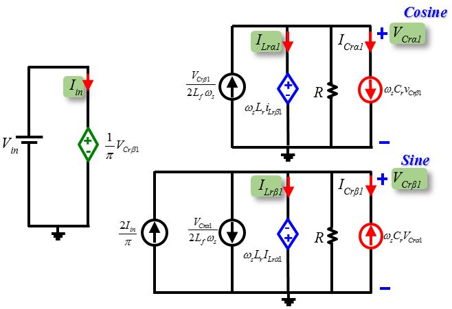
The Time-Invariant Multifrequency (TIMF) Modeling technique is utilized to account for the DC and first harmonic of the power amplifier. The corresponding steady-state circuit model is also derived for easier comprehension and use (as shown in Fig. 2). Based on the circuit model, the sine and cosine coefficients of the currents and voltages can be determined. When switching at resonant frequency, tank voltage is purely sine wave (see Fig 1) and the cosine part of v
Cr(t) should be zero. Based on the modeling results, the resonant frequency is determined. Such frequency depends not only on the tank's inductor and capacitor, but also on the filter inductors. With sufficiently large L
f, the resonant frequency can be approximated by natural frequency. Whereas, with decreasing L
f, the deviation of the resonant frequency from natural frequency will increase. If still switching at natural frequency, the effective resonant tank is "inductive" and causes a large current spike.

Fig. 2. Steady-state circuit model of power amplifier


