


LIBRARY
Resistance Compression T-Networks with Active-Switch Compensation in the Input Branch for Constant-Frequency Resonant Power Conversion
Year: 2015
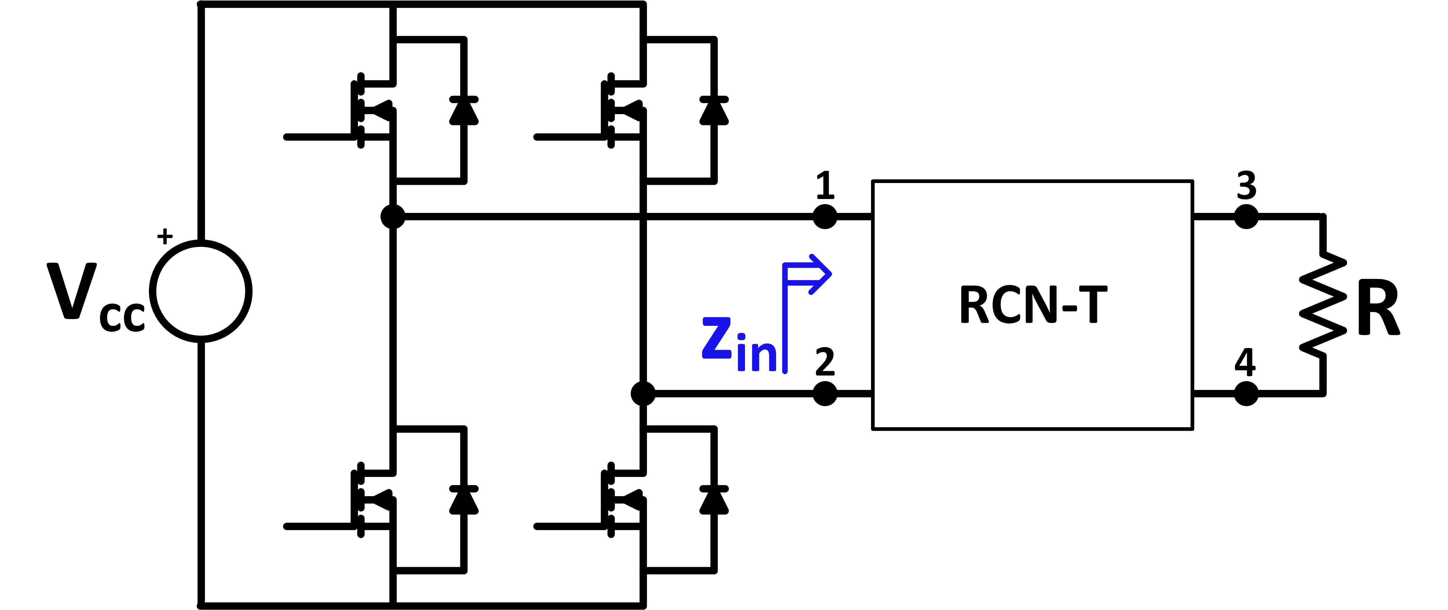
Fig. 1. Resonant inverter equipped with an RCN-T.
Active compensation is required in the input branch of the T-type network in order to create an effective RCN-T circuit. The compensator consists of a four-quadrant switch and a parallel capacitor (Fig. 2a-2c). This configuration ensures ZVS turn-on of the switch and near-zero switching losses.
Depending on the voltage ratio between the input and the output of the RCN-T, three classes of circuits are possible: buck, buck-boost, and boost. Buck RCN-T is associated with the compensated LLC resonant tank in Fig. 2a. Buck-boost functionality is obtained with the compensated LCL tank (Fig. 2b). Compensated LCC tank in Fig. 2c has boost functionality. Filtering capability of the RCN-T network is necessary to reduce the component count and cost, and to improve the simplicity of the system. Fig. 3 shows typical bode plots of the input impedance for each class of RCN. The buck class has only a limited capability to filter the higher frequency component, necessitating additional filtering to ensure proper operation at the operating frequency (Fig. 3a). The buck-boost class does not have any filtering capability (Fig. 3b), and it is as disadvantageous as the buck class. The boost class (Fig. 3c), on the other hand, has intrinsic filtering capabilities. For this reason, boost topology is most attractive for the design's implementation.
The full paper incudes the design procedure of the RCN-T boost system. Conduction losses of the active switch are further minimized by the properties of the boost class and compensator used, ensuring that RCN-T efficiency will be in the high 90% range.
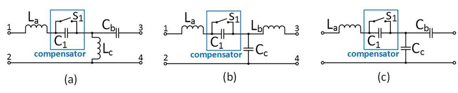
Fig. 2. Capacitive compensator at the input branch of the T-networks: (a) LLC; (b) LCL; (c) LCC.
.jpg)
Fig. 3. (a) Typical Bode-plots of the RCN-T's input impedance zin for each class: buck.
.jpg)
Fig. 3. (b) buck-boost.
.jpg)
Fig. 3. (c) boost.
