


LIBRARY
Modular Multilevel Alternate-Arm Converter (AAC): Modeling, Design and Control
Year: 2015
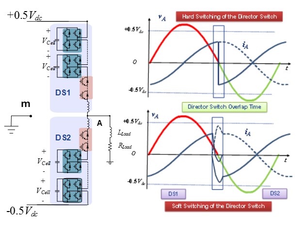
Fig. 1. Zero Current Switching Realization in AAC vs. Hard Switching
In Fig. 1, the hard switching vs. soft switching of the DS in the AAC is shown. It can be seen from Fig.2, by using the overlap time between the upper and lower arm director switches, that the current through the resonant LC circuit can go to a negative value and the ZCS can be achieved. During the overlap time, all the cell's capacitors will be inserted positively to the arm, and the difference voltage of the DC link and arm voltage, which is negative will be put over the arm in-ductor. This voltage makes the current through the arm become negative and provides a Zero Current Switching condition for the DS.
The simulation analysis has been done through Simulink/ Matlab to verify the proposed scheme for Zero Current Switching, and the analytical analysis of the capacitor voltage ripple, as well as the operation of the AAC in the RL loads. The simulation has been performed for the load power factor φ=37° resistive and the inductive load RL. The upper and lower arm currents wave-forms as well as the upper and lower arm capacitor voltage, the phase and DC line current is shown in Fig.2. The results show that the AAC, despite having a higher number of switches, will have less switching power losses. This is mainly due to the lack of circulating current, the alter-nating of the load power, and also the use of the demonstrated ZCS scheme for the Director Switches.
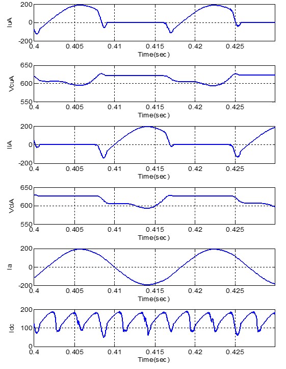
Fig. 2. Arm, DC and Phase Current and cap voltages of AAC with ZCS of DS for load power factor φ=37°
