LIBRARY
GaN-based High Frequency Totem-Pole Bridgeless PFC Design with Digital Im-plementation

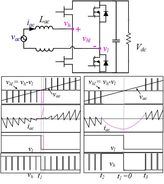
Fig. 1 shows the schematics of this topology. In this investigation, all four switches in the H-bridge are active switches. The low frequency (LF) phase leg only commutates at line frequency, while the high frequency (HF) phase leg will chop the DC voltage at high frequency. In this case, the low frequency phase leg can use very large Si MOSFETs, and thus the on-resistance can be reduced. The HF phase leg is built with GaN devices.
The first issue when using this topology is addressing the significantly different switching speeds of the HF leg and LF leg switches. From the bottom-left chart in Fig. 1, we can see that when the voltage transition of the LF leg has a certain delay, the DC link voltage will directly apply across the AC inductors, causing a current spike. This delay is equal to the dead time of the LF leg. The second issue of this topology deals with the minimum pulse width of the HF leg. At zero-crossing, the duty cycle of the HF leg needs to change abruptly from 100% to 0%. However, the phase leg cannot output such narrow or wide pulses, so those extreme pulses are eventually blanked as high or low levels. Thus, AC voltage is applied across the AC inductor for multiple switching cycles, leading to current spike.
By carefully designing the digital modulator, the two aforementioned issues can be resolved. A lead-time of dead time length is programed in the ePWM module so that the delay of the LF leg is compensated for. The second issue is resolved by digital dithering. The PWM pulses are delivered in a batch of ten. If some of the pulses are skipped in one batch, then the equivalent pulse width of the batch is increased by ten.
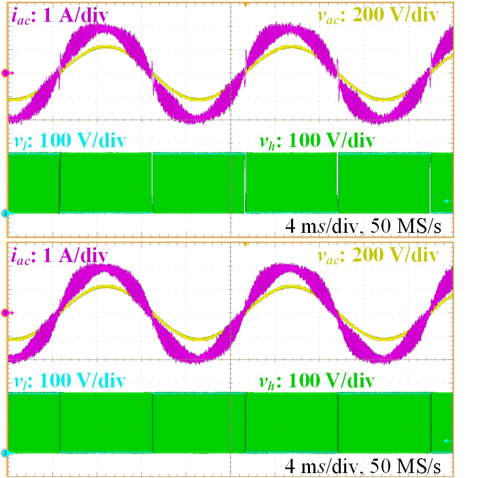
Without improvement of the digital modulator, a current spike can be observed at the zero crossing of the AC voltage, as shown in the upper portion of Fig. 2. After implementing both LF leg compensation and HF leg dithering, the current spike is eliminated (Fig.2 bottom). This work provided solutions to the inherent issue of current spike of the totem-pole bridgeless PFC converter. These solutions could prove even more important when AC inductance is reduced further due to higher switching frequency.


