


LIBRARY
Steady-State Analysis of Voltages and Currents in the Modular Multilevel Converter Based on an Average Model
Year: 2015
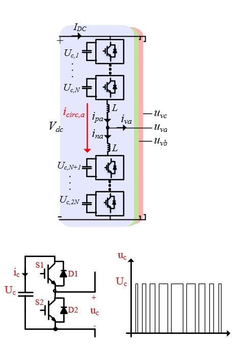
Fig. 1. (a) Three-phase MMC inverter and (b) Half-bridge submodule as building-block of MMC AFE
The wide variety of applications, along with the need for a significant amount of passive elements installed, requires the best possible MMC converter design. In order to understand the operation of the MMC and then design the converter for the target application, an accurate analysis of the voltage and current waveforms in the MMC are of great importance.
In this paper, a detailed analysis of submodule voltages and arm currents is done based on an average model. The analysis takes into consideration the arm current components up to the 4th, and submodule voltage ripple components up to the 5th, harmonic. Also, the resonant behavior of the 2nd and 4th order harmonics in the circulating current is investigated and the relationship between resonance frequency and the magnitude of passive elements is derived. Then, a guideline to select the size of arm inductance and submodule capacitance is discussed. Finally, validity of the derived equations is shown via simulations in MATLAB/Simulink.
