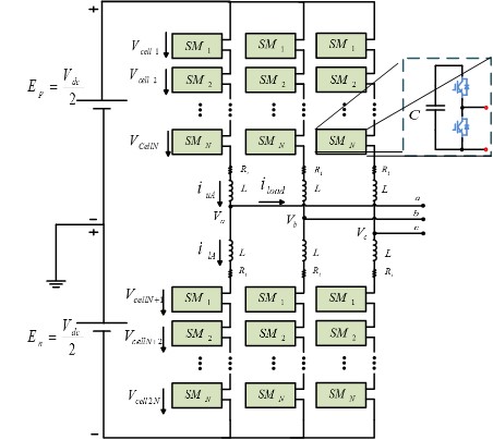
Fig.1. Modular Multilevel Converter topology with each power module structure
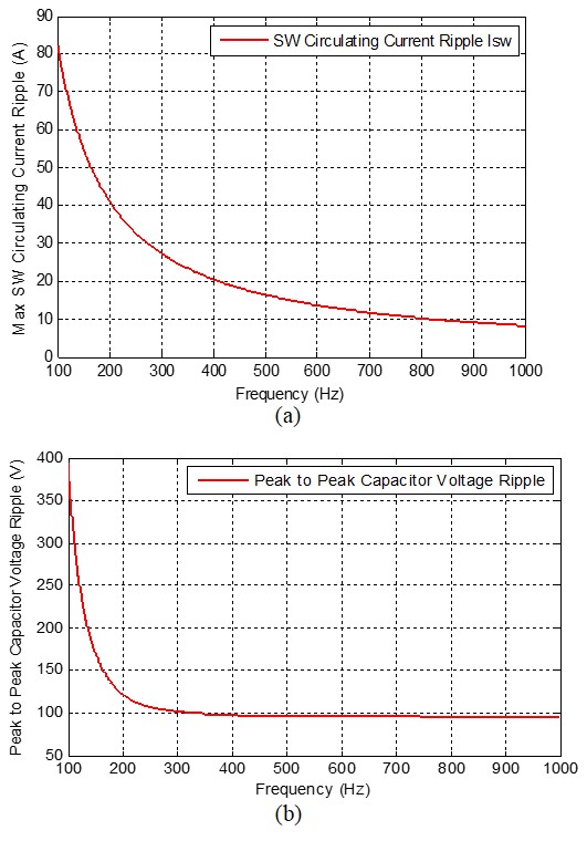
Fig.1 shows the Modular Multilevel Converter (MMC) topology with each power module structure. In order to reduce the switching loss of the converter in high and medium voltage applications, it is preferable to operate at a low switching frequency. The consequence for this is an increase in the circulating current magnitude and harmonic distortion. In Fig. 2, the switching frequency effect on the arm current and the voltage ripple of the capacitor are shown. As seen in this plot, the switching ripple of the arm current and the capacitor voltage increase significantly at a lower switching frequency. Therefore, choosing the switching frequency for the MMC is effectively a tradeoff between the IGBT power loss and the maximum allowable voltage, and the current ripple through the module capacitor and the phase-arm inductor. To obtain the optimum switching frequency for the MMC, the reliability of the converter is selected as the objective function.
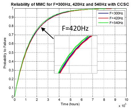
Fig. 3 shows a plot of the probability to fail in time for the MMC operating at a switching frequency of 300 Hz, 420 Hz and 540 Hz with CCSC. The 420 Hz case achieves the best reliability performance, although only a minor overall impact is determined. Nonetheless, this result points out that although less semiconductor losses are incurred when operating at lower switching frequencies, the increase of the voltage ripple across the capacitors and IGBTs can detrimentally affect the reliability of the converter. This illustrates one of the key tradeoffs when designing the MMC.

Fig.2. With respect to frequency, (a) switching ripple of the arm current and (b) capacitor voltage

Fig.3. Markov Reliability Model of the MMC with Circulating Current Suppressing Controller in different frequencies


