


LIBRARY
Analysis and Simplification of Modular Multilevel Converter and Circulating Current Injection
Year: 2015

Fig.1 (a) capacitor voltage without injecting (b) capacitor voltage with injecting
One method for reducing capacitance is injecting a 2nd order circulating current. In an MMC system, there is a circulating current in the phase arm, which includes a second order and a higher order harmonic. Meanwhile, on the capacitor, there exists power with a second order harmonic that is closely related to capacitor voltage ripple. By controlling the duty cycle, the circulating current can be modulated to be a given second order harmonic. With that circulating current, the second harmonic of the power in the capacitor can be eliminated. Hence, the capacitor voltage ripple can be suppressed as shown in Fig.1. As a result, given the pre-vious voltage ripple tolerance, a smaller capacitance can be used. However, the RMS value of the arm current will increase and along with it, the loss.
Another method for reducing capacitance is injecting high frequency common mode voltage and circulating current. This works only for a three-phase MMC system. In a three-phase MMC system, there are currents that circulate among three phases, and a common mode voltage in the neutral point of the three phases. These are two factors to consider in realizing high frequency power flow. The capacitor's energy fluctuation has an inverse rela-tionship with its power frquency, which also means that a higher frequency power results in a smaller capacitor voltage ripple. The resulting suppression of the voltage ripple is shown in Fig.2. This method works especially well in a low modulation index situation, such as a motor drive.
In both of the methods discussed above, reducing capacitor voltage ripple usually results in a higher arm current RMS value. Therefore, the tradeoff between capacitor size and loss should be considered carefully.
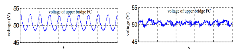
Fig.2 (a) capacitor voltage without injecting (b) capacitor voltage with injecting
