


LIBRARY
Design of 3.3 kW Wireless Inductive Power Transfer System
Year: 2015
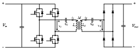
Fig. 1. Topology of the designed 3.3 kW WIPT system, with primary side full bridge inverter, series-series resonant tanks, and secondary side diode bridge
The coil design includes optimization of coil structure, and selection of inductance, and calculation of AC resistance. Circular planar coils with ferrite plates placed below are used, and the coupling coefficient between the transmitter and receiver can achieve 0.25 when perfectly aligned. The range of the inductance value is selected based on the operating frequency range (90 - 110 kHz) and the power requirement (Pout = 3.3 kW). The turns number is tuned to change the self-inductance within the selected range for an optimized coupling coefficient, winding loss, and density. The AC resistance of the coils is calculated based on the Bessel function, with magnetic field information from an FEA simulation.
Resonant capacitors face the problem of high voltage stress up to 1.3 kV RMS value at 100 kHz. To solve this problem, a capacitor bank of film capacitors is applied, with 87 capacitors on the primary side and 38 on the secondary side. Calculations show that the conduction loss on the resonant tanks is 1.8% for 400 V output and 3.3 kW output power.
Frequency control is implemented for the primary side inverter. The hardware of the inverter is shown in Fig. 2. When the output voltage or coupling coefficient changes, frequency has to be adjusted for 3.3 kW output power. Soft switching is achieved for turn-on due to the coils' de-sign for operating frequency range, and hard switching for turn-off. Experimental results prove that 95% efficiency is achieved for 3.3 kW output power.
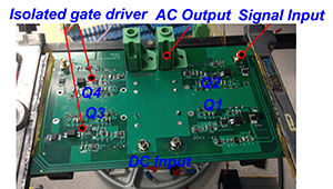
Fig. 2. Hardware of the full bridge inverter used for the WIPT system and waveforms for its output voltage and current
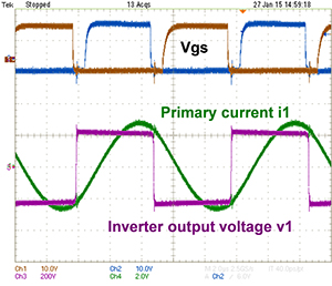
Fig. 2. Hardware of the full bridge inverter used for the WIPT system and waveforms for its output voltage and current
