


LIBRARY
A Novel Phase Lock Loop (PLL)-Based Interleaving Structure for Variable-Frequency Controlled Voltage Regulators
Year: 2015
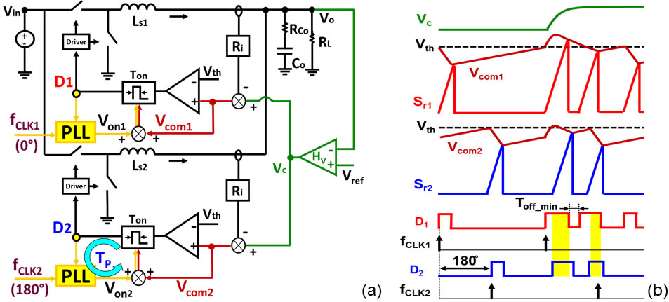
Fig. 1 Proposed PLL-based RPM control
This paper proposes an interleaving method incorporating PLL to solve all above issues. Fig 1(a) shows the dual-phase configuration, where two PLL forces D1 and D2 follow two fixed-frequency clocks (fCLK1, fCLK2) in 180° phase shift by slowly adjusting on time through on-time control signals (Von1, Von2). The benefits are as following: firstly, D1 and D2 can be naturally overlapped to speed up the load transient, as shown in Fig. 1(b); secondly, since Vc compares with the individual phase current, the current feedback does not suffer a ripple cancellation; thirdly, since the steady-state fsw is locked with fCLK, so VR can operate at an optimal efficiency point; fourthly, the beat frequency ripple current is eliminated by synchronizing the clock frequency of every VR controllers in a multi-processor motherboard.
The loop gain of the PLL loop (TP) in Fig. 1(a) is analyzed by a proposed small-signal model, and the compensation guideline is provided. Moreover, enlightened by the model, an adaptive PLL loop is presented to simplify the loop compensation by auto-tuning the control bandwidth anchored at the peak phase margin, as shown in Fig. 2. After that, a hybrid interleaving technique, a combining pulse distribution method, and a PLL method are developed to significantly reduce the circuit complexity by using the PLL loop for the high phase number application, all while transient performance remains comparable. Finally, the simulation and experimental re-sults verify the proposed method.
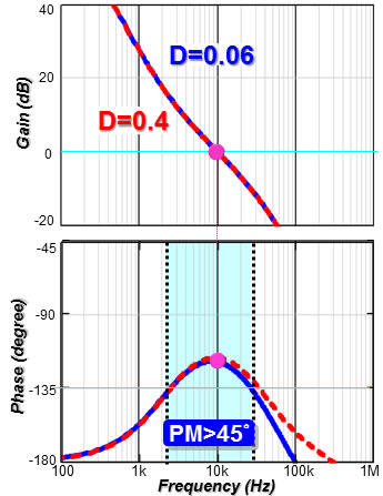
Fig. 2. Tp of adaptive PLL loop
