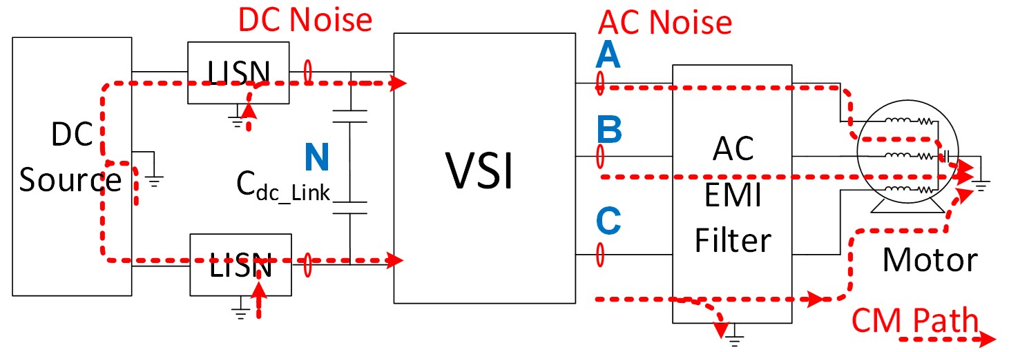
Fig. 1. DC-fed motor drive system with EMI Filters
In dc-fed motor drive systems as shown in Figure 1, EMI filters are inevitable parts that provide EMI noise attenuation to avoid interference between different components. In the EMI filter de-sign process, inductor volt-second is an important design condition for inductor optimization. In order to predict the volt-second for inductor optimization, a frequency domain prediction model is proposed. The noise source can be calculated using a double Fourier integral transformation method, and the propagation path impedance can be directly measured from the system or cal-culated based on the impedance model in frequency domain. With the proposed model, inductor volt-second can be predicted accurately and the model is verified through experimental tests.
In real applications, dead time is necessary to avoid a shoot-through error in the converter. Dead time (DT) will change the voltage noise source in the prediction model as shown in Figure 3, therefore it also changes the volt-second on the inductor. Figure 4 shows the impact of DT on inductor volt-second with continuous SVM modulation method. The results show that the impact of dead time on inductor saturation is related to system modulation methods, dead time value and also the value selection of the inductors and capacitors of the EMI filters. The dc-fed motor drive system with an output EMI filter is chosen as an example, and the analyzing method can also be applied to other converters.
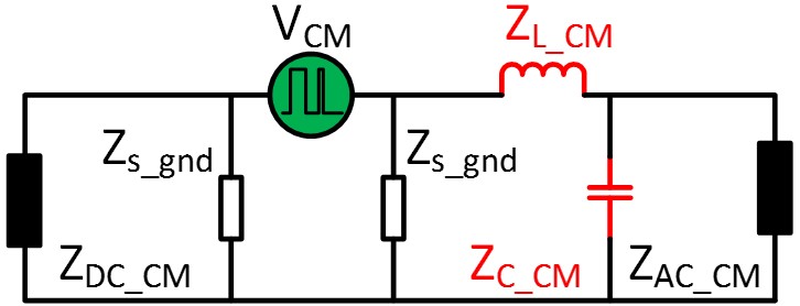
Fig. 2. 1 Inductor volt-second prediction model
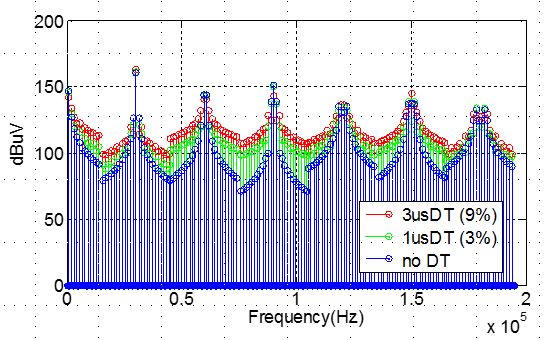
Fig. 3. Voltage spectrum change with dead time
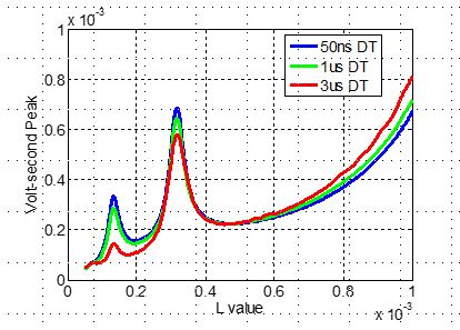
Fig. 4. Impact of DT on inductor volt-second
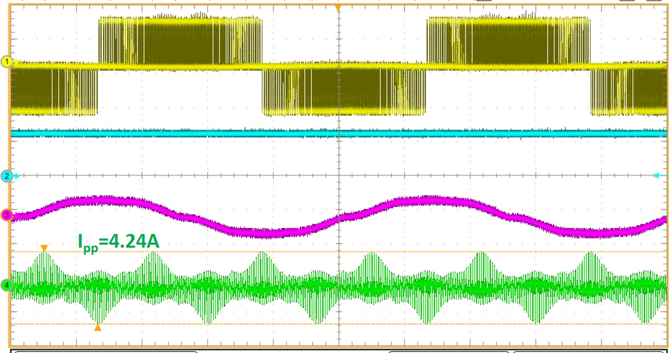
Figure 5. 150 uH EMI filter test results (Vdc=270 V) (Vab: yellow (200V/div); Vdc: Blue (200V/div); Iout: pink (20A/div); Icm_L: green (2A/div)) (a) 1us DT


