


LIBRARY
A 50 kW SiC Three-Phase AC-DC Converter Design for High Temperature Operation
Year: 2016
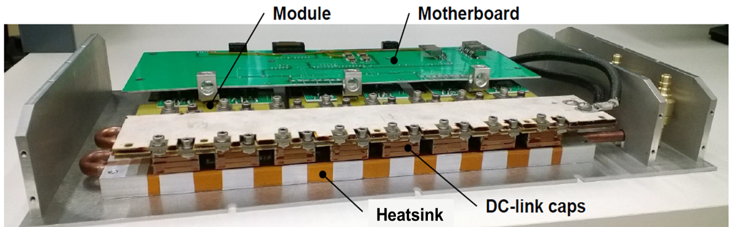
Fig. 1. Constructed 200 C 50 kW three-phase ac-dc converter.
In this work, a 50 kW three-phase ac-dc converter capable of 200 °C-ambient operation was designed and tested (Fig. 1).
To meet the 50 kW power requirement, each single phase-leg module in the converter should have a rating of at least 1200 V and 100 A. However, at the time none of the commercially available high-power modules were designed for >150°C. This was mainly due to the temperature limitations of the packaging materials. Therefore, a customized 1200 V, 120 A SiC MOSFET phase-leg module was designed and fabricated with careful selection of the packaging materials to allow for operation in 200 °C ambient environments. The module layout was also optimized such that it could be utilized in high-frequency converters with a fast switching speed, while having minimal device stresses.
To drive these modules, the HADES half-bridge isolated gate driver circuit from Cissoid was used. This gate driver can operate in 175C ambient environments with short excursions up to 225C. Other features include an isolated regulated power supply, 4 A peak output current, 30 kV/µs typical transient immunity, under-voltage lock out, and desaturation detection.
Double-pulse tests (DPTs) were performed at 200 C ambient, 540 V, and up to 115 A (Fig. 2) in order to assess the HT switching performance of the converter. Due to the lack of HT voltage probes, the gate-source and drain-source voltages were sensed from long HT twisted wires extending from the HT environment. The long length of these HT wires resulted in substantial ringing in the gate-source and drain-source waveforms (Fig. 2). Room-temperature DPTs verified that the ringing was due to the wiring, and was not the actual voltages seen on the converter.
.png)
Fig. 2. Turn-on
.png)
(bottom) DPT wave-forms at 200 C ambient temperature, 540 V, and 115 A, with an external gate resistance of 3.3 ω.
