LIBRARY
Electro-Thermal Distribution among Paralleled SiC MOSFETs
.jpg)
Simulation is based on LTspice. Compared with traditional simulation, electro-thermal simulation is more accurate for the simulations that involve temperatures. However, mismatch information cannot be found in the Spice model provided by the manufacturer. After modifying, the Spice model of SiC MOSFETs with mismatch in the threshold voltage (Vth) and on-resistance (Rds(on)) are created. The range of mismatches is obtained from a technical report from the manufacturer. After that, two paralleled SiC MOSFETs with a mismatch are applied in a boost converter in LTspice to test the temperature and current unbalance. Furthermore, to reduce the unbalance, a Newton-Raphson iteration-based calculation, which has little operating time and calculation error, is applied to replace time-consuming electro-thermal simulation. The current and temperature distribution among two paralleled SiC MOSFETs can be obtained by looking at Fig. 1.
Considering that in a SiC MOSFET a temperature rise causes Rds(on) to increase and Vth to decrease, the positive temperature coefficient (PTC) of Rds(on) can help balance the difference in conduction loss. However, although it seems that a negative temperature coefficient (NTC) of Vth will degrade the switching loss balancing with a higher temperature, in simulation the difference in switching loss is almost constant with temperature increasing. To summarize, the difference of switching loss caused by a mismatch of Vth is the source of unbalance in temperature, and the PTC of Rds(on) is the intrinsic balancing ability in SiC MOSFETs. Whether the PTC can compensate the unbalance is determined by the ratio of the switching loss and conduction loss. If the conduction loss is high enough, the balancing ability caused by PTC is strong enough to compensate the power difference, and vice versa.
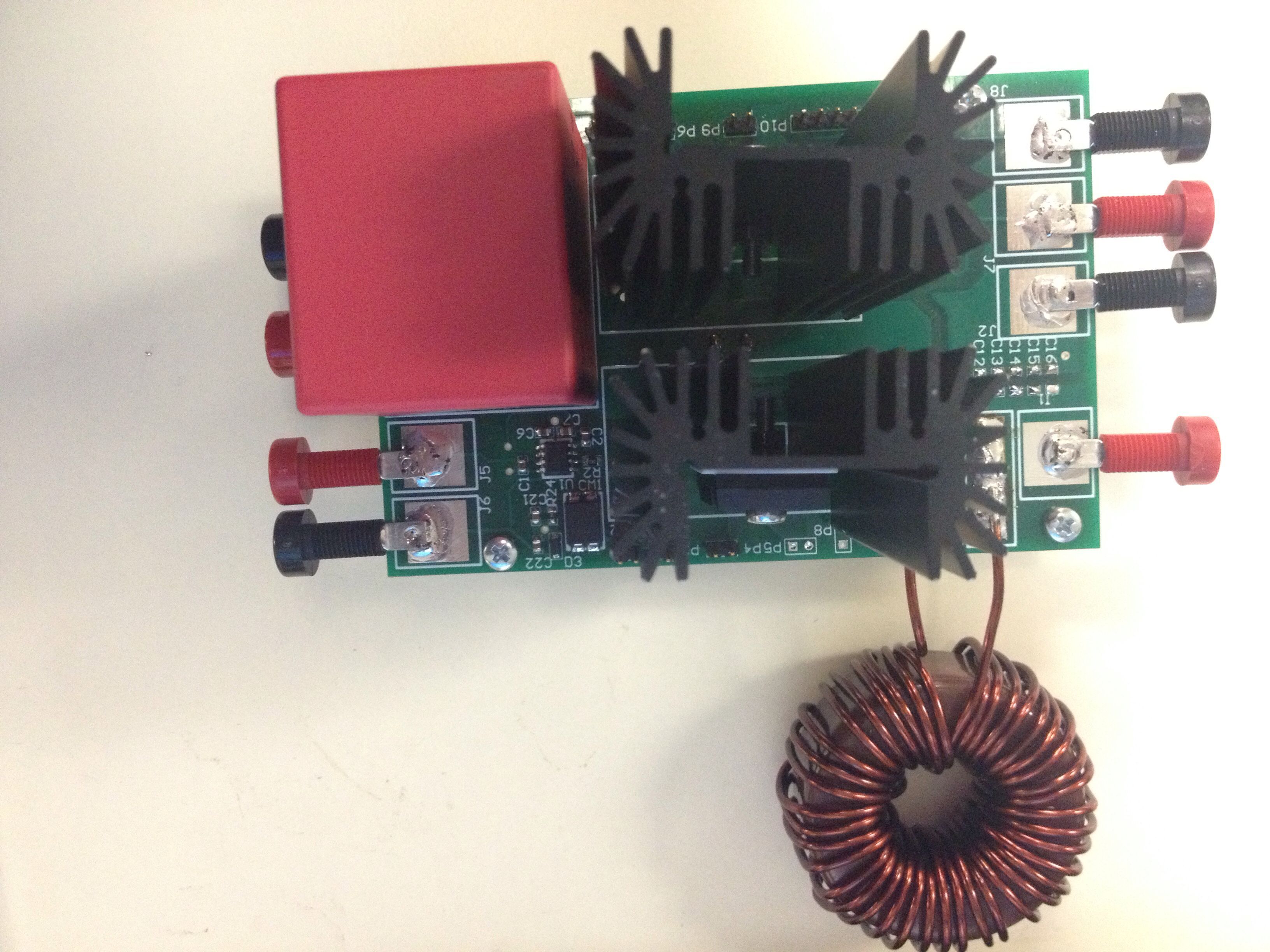
A two-level experiment is used to verify previous analysis and calculation results. First, the component parameters are measured to verify the previous mismatch range and re-guide simulation (calculation). Based on the previous measurement, samples with obvious mismatches are inserted in a boost converter to verify the calculation results in regard to current and temperature distribution. The experiment platform is shown in Fig. 2.
.jpg)


