LIBRARY
High-Frequency Isolation Solution for DC distribution Data Center
Year: 2016
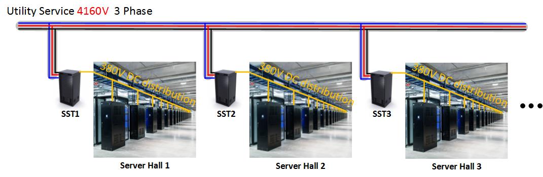
Fig. 1. Proposed power architecture for future data center.
With the advent of the new generation of SiC and GaN devices, we propose to operate the DC/DC stage at an unprecedented high frequency: 500 kHz, which is 25 times higher than industry state-of-the-art SSTs. At 500 kHz, the selection of WBG devices and converter topologies are critical. A novel bi-directional CLLC resonant converter will be employed, instead of the popular back-to-back connected dual-active bridge. Each DC/DC module will be designed to handle 15-20kW power.
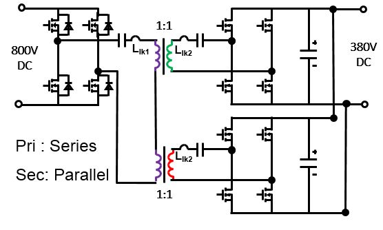
In order to reduce secondary-side conduction loss, two output sets are paralleled to handle the high output current, as shown in Fig. 3.
For such a 4160V AC to 380V DC system, insulation is critical for the overall system. This function is implemented by the isolated DC/DC converter. Since the insulation design for this high-frequency transformer is crucial, we propose using a sectionalized coil structure to guarantee enough clearance and creepage distance between the primary and secondary windings.
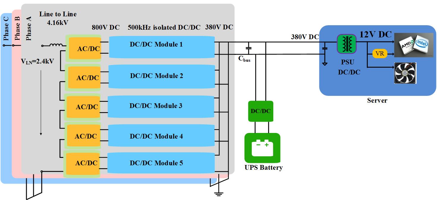
Fig. 2. Three-phase solid state transformer (SST) system.