LIBRARY
Study on Three-level DC/DC Converter with Coupled Inductors

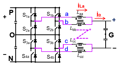
With one integrated coupled inductor, as shown in Fig. 1, the power density can be increased to be higher than the conventional solution of two coupled inductors. Based on the small-signal model of the three-terminal switch, the small-signal model of the converter is derived in Fig. 2. The result indicates that the integrated coupled inductors can be decoupled during transient response, assuming it is a symmetrical structure. Comparing this with a conventional buck converter, it is obvious that the only difference is the equivalent inductance, 4Mac Llk. In other words, only the positive coupling mutual inductance and the leakage inductance determine the small-signal characteristics. The negative coupling between arms a and b and between arms c and d is designed to suppressed the circulating current in the converter and reduce the inductor current ripple.
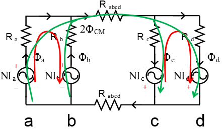
To fully understand the integrated coupled inductors and provide guidance for design, the flux is separated into a common-mode part and differential-mode part in the magnetic circuit, as shown in Fig. 3. In this diagram, the red curve represents the negative coupled flux (DM flux) between arms a and b and between arms c and d. The green curve (CM flux) represents the positive coupled flux among the four arms. The analysis of this magnetic circuit indicates that the negative coupled flux is pure large AC ripple, and related to the tolerable core loss density. The positive coupled flux is a large DC flux plus a very small ripple and directly determined by the output current, which indicates that there would be a potential core saturation problem under certain working conditions if it is not properly designed. There will be trade-offs between core loss and saturation limitations for different magnetic materials of the core.


