LIBRARY
Equivalent Circuit Modeling of LLC Resonant Converters
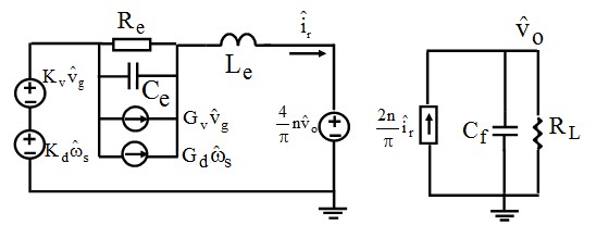
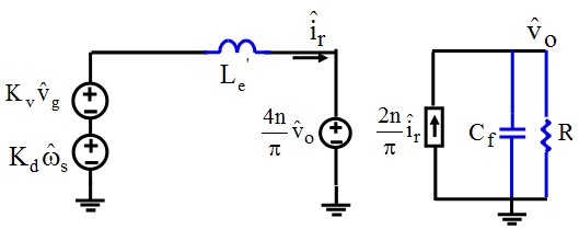
For LLC converter ZVS, the resonant tank behavior differs depending on the operating frequency. For Fs Fo, only Lr resonates with Cr, and Lm is clamped by the output voltage. For Fs < Fo, there is some time period that Lm also participates in resonance. Due to different resonant behaviors, small-signal models are developed for each case, and the resulting non-coupled equivalent circuit models are shown in Fig. 1 and Fig. 2. A unified equivalent circuit model is then derived for both cases, as shown in Fig. 3. The resulting circuit represents a third-order system by which all the transfer functions can be easily derived.
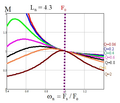
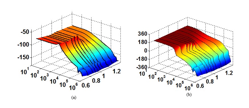
By the aid of the unified model, we can plot an accurate DC gain curve to compare to the traditional fundamental analysis and a 3D plot for the control-to-output transfer function, as shown in Fig. 4 and Fig. 5. An insight analysis is also presented in this work that describes the dynamics of the converter in different operating regions. When the switching frequency is larger than the resonant frequency, the beat frequency double pole shows up and the circuit is third-order; when the switching frequency is close to the resonant frequency, the beat frequency double pole disappears, and a new double pole appears, formed by equivalent inductor Le and equivalent output capacitor Cf. The circuit then reduces to second order. When Fs < Fo, Lm participates in the resonance and the circuit is essentially a multi-resonant structure.
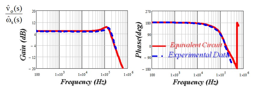
Figure 6 shows the experimental verification of the control-to-output voltage based on the unified equivalent circuit model, as the small-signal model matches very well with the experimental data.
