


LIBRARY
State Trajectory Analysis of Modular Multilevel Converter
Year: 2016
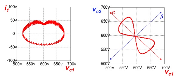
Fig 1. State Trajectory with simple control law
In simple duty cycle control law, the duty cycle was set in order to produce a purely sinusoidal output. In Fig.1, the loop size of figure (a) represented the upper module output energy in one line cycle. That energy was the dominate reason of the capacitor voltage ripple. In Fig.1, the picture (b) on the right hand side showed the power transfer of upper and lower arm module. The relationship of upper module capacitor voltage vc1 and lower module capacitor voltage vc2 various in axis and β axis. The axis represent energy swapping between upper and lower modules. The β axis represent the module energy transfer with load and source simultaneously. . The state trajectory was a result of the combined effects of both two axis.
In order to reduce capacitor voltage ripple, 2nd order circulating current can be inject to eliminate the 2nd order power of module. 2nd order power of module transferred only from module to load and source. In state trajectory, this power effected only the β axis. When the 2nd order harmonic power of module was reduced to zero, the state trajectory of vc1 and vc2 should have no distant at β axis. As in Fig.2 picture (b) shown, the state trajectory was only shaped by axis. That mean the only reason of capacitor voltage ripple was the energy swapping between upper and lower modules.
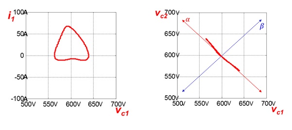
Fig. 2. State trajectory with 2nd order harmonic circulating current injection
