


LIBRARY
Testing of a Novel Medium-Voltage Impedance Measurement Unit
Year: 2016
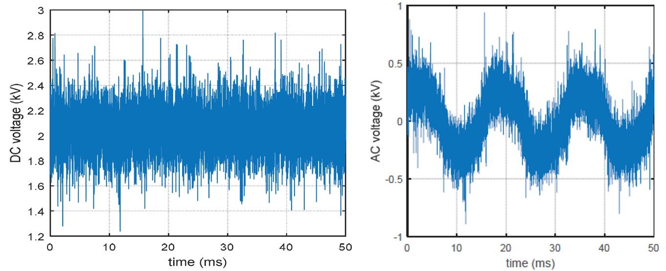
Fig. 1. (a) DC voltage and (b) AC voltage example during PEBB power stage testing.
Three major test setups are of primary interest: the basic Power Electronics Building Blocks (PEBB)-based modules of the IMU are tested for voltage and current capabilities, AC impedance measurement in a three-wire AC system, and DC impedance measurement.
The PEBB tests were successfully executed, and heat runs were performed to confirm the design. Examples of DC and AC voltages conditions are shown in Fig. 1. The PEBBs were operated with up to 4 kV on the DC side and a modulation index commanded to generate AC voltages.
Fig. 2(a) shows the load impedance as measured by the IMU in the AC setup while operating at 480 Vac. The result reflects to a large part the connected resistive load with some inductive components. The IMU operation has to take place in an environment that shows switching level distortions at various levels: Fig. 2(b) shows the AC voltage and current as measured with a 10 kHz low-pass filter (normalized quantities). The voltage and current have been recorded while perturbing the AC system at 680 Hz, and the surrounding system shows significant levels of common-mode currents and distortions in voltages and current.
The next tests will evaluate the IMU capabilities when connecting one of the MMCs as the load rather than the passive load bank. The MMC connected to the IMU acts as the AC/DC converter, and another MMC will be used to set the DC system loading conditions.
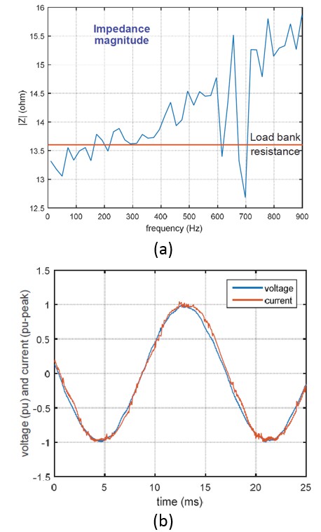
Fig.2. (a) Example AC impedance measurement result and (b) Example AC voltage and current waveforms while IMU injects perturbation
