LIBRARY
Small-Signal Terminal Characteristics Modeling of Three-Phase Boost Rectifier with Variable Fundamental Frequency

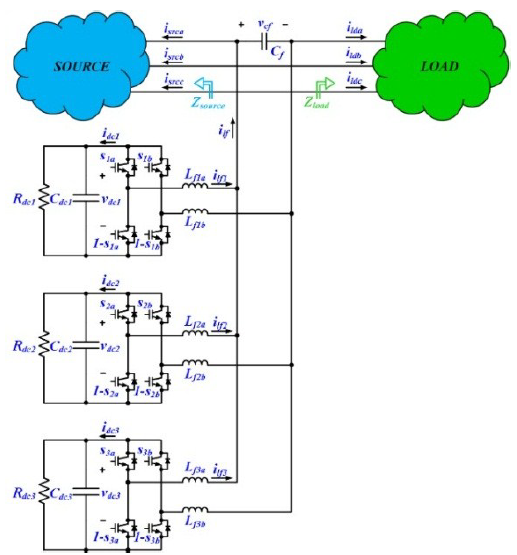
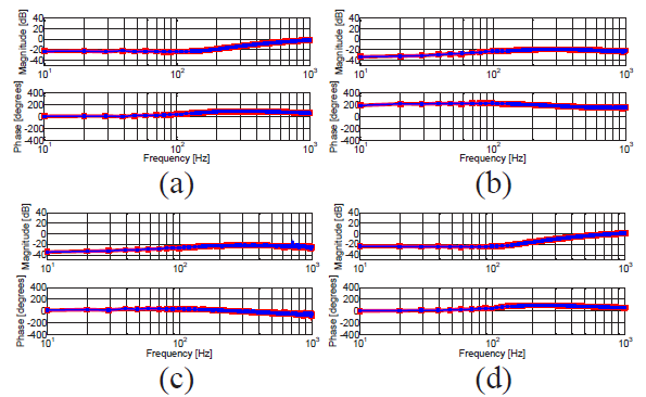
The interleaved transformerless H-bridge converter (Fig. 1) is optimized to operate as a series voltage injector, increasing the low-frequency injection range by avoiding transformer saturation problems. Decoupling control is implemented, providing an effective way to balance dc capacitor voltages and regulate the series injection voltage. The modular and scalable single-phase impedance measurement unit (IMU) is designed and constructed to inject chirp, multitone and sinusoidal signals in series with the three-phase ac power systems. The measurement system is designed to inject all three types of signals in the full frequency range, offering a trade-off between measurement time, precision, and the number of identification points. The effectiveness of the proposed identification approach is verified with an online estimation of source and load impedances of an actively controlled, programmable voltage source and a three-phase resistive load, as shown in Fig. 2.


