LIBRARY
Wide-bandwidth Identification of Small-Signal dq Impedances of ac Power Sys-tems via Single-Phase Series Voltage Injection

In several emerging applications of AC power electronics system, such as micro-grids, the droop control is very popular for power sharing among the parallel power sources, where the droop between active power and fundamental frequency, and the droop between the reactive power and the voltage magnitude are usually implemented. This means that the fundamental frequency of such a system will be varied with the load power, and the coupling between the source and the load not only includes the voltage and the current in SRF, but also covers the fundamental frequency.
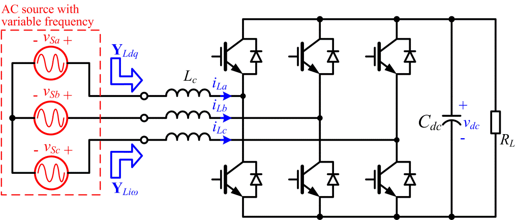
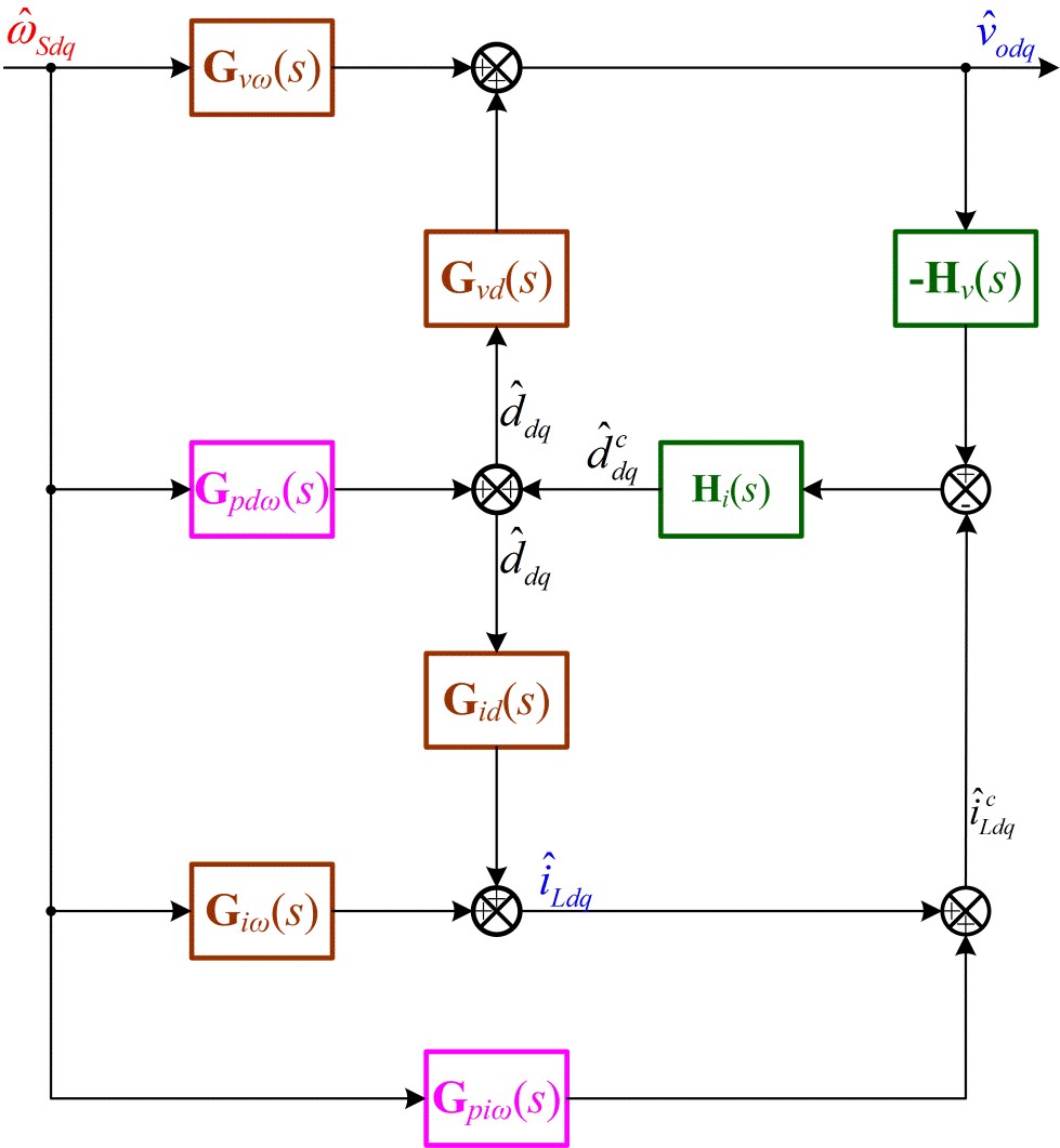
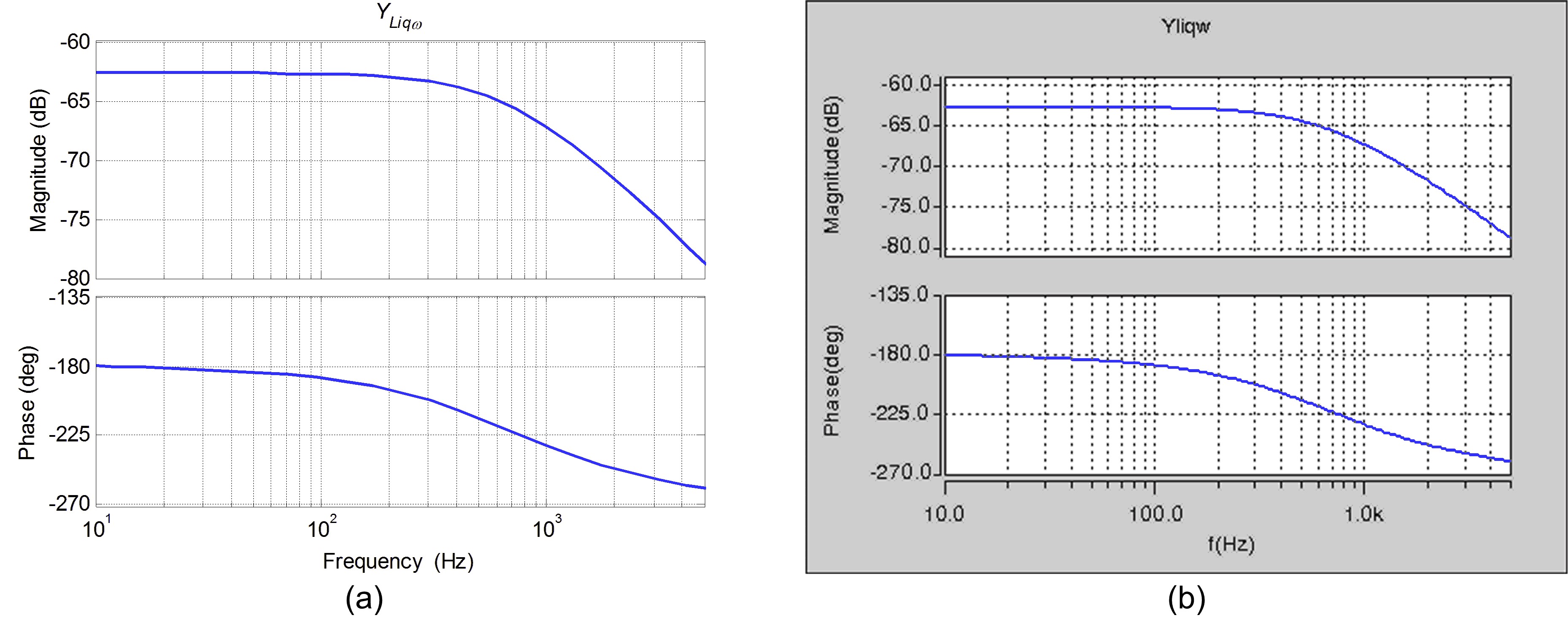
As an AFE of the load in the AC power electronics system, the three-phase boost rectifier in Fig. 1 is widely employed, and thus its terminal characteristics regarding the variation of fundamental frequency are studied. Its small-signal model considering the dynamic behavior of the fundamental frequency is proposed as shown in Fig. 2. Here, it is revealed that the dynamic of fundamental frequency is introduced by both the fundamental voltage drop of the filter inductor and the PLL. The transfer function of the terminal characteristics from fundamental frequency to input current in SRF is derived, and verified in frequency domain. These bodeplots are partially shown in Fig. 3. The proposed model can be applied for the stability analysis of the system with variable fundamental frequency.


