


LIBRARY
Magnetic Material Selection Procedure for a Coupled Inductor used in Interleaved Three-level Multi-phase DC-DC Converters
Year: 2016
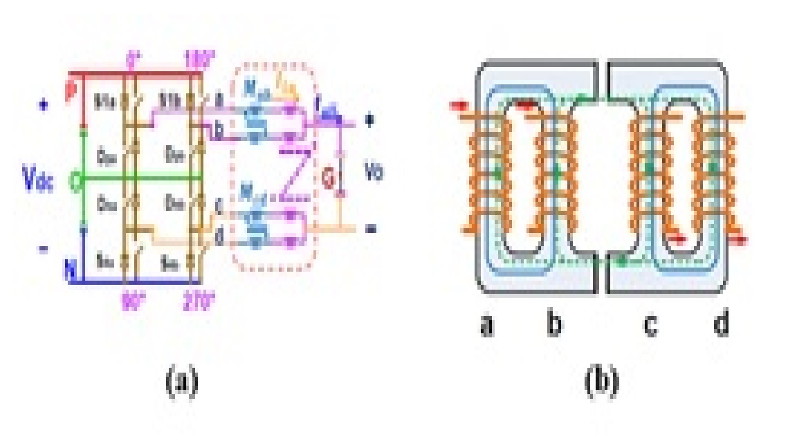
Fig. 1. (a) Three-level DC/DC converter with integrated coupled inductor (b)Integrated core structure (concept drawing)
In this work, a new design is proposed to integrate the two coupled inductors as one magnet-ic component. The schematic is shown in Fig. 1(a), where the inductors to be integrated are shown in the red box. The concept drawing of the new structure is shown in Fig. 1(b). This inte-grated inductor can achieve the purpose of suppressing circulating current and boosting output inductance at the same time.
With high-frequency operation, amorphous and nanocrystalline materials are good candidates for the magnetic core due to their low core loss and high saturation. These two types of materials are usually produced in the form of a tape-wound core, so the flux must flow in the direction of the lamination layers. The structure in Fig. 2(a) is proposed to realize the concept drawing of Fig. 1(b). Fig. 2(b) shows the different flux paths for different parts of the core.
After calculating the required output inductances to minimize switching loss and output capacitor size, the different mutual inductances can be calculated. This corresponds to a certain flux in each leg, which is divided into two components; the BCM is a large DC flux with a very small rip-ple, and the BDM is a large-amplitude AC flux. These two flux components have to be limited to a certain range determined by the allowable saturation level in each leg and the generated core loss.
To optimize the core size and weight, the product of N (number of turns) and Ae (equivalent core cross-section area) should be minimized with the previously mentioned constraints. A de-sign procedure is proposed in this work, with two material candidates for high-power applica-tions; iron-based Amorphous has a higher saturation limit (1.56T, Metglas®2605SA1), while Nano-crytalline has lower core loss but a lower saturation limit (1.2T, FINEMET®). Fig. 3 shows the N Ae variation for the two materials with different operating voltages and currents with a fixed inductance, operation frequency and duty ratio. From this we can conclude that minimizing the size of the core is not only dependent on the material but also on the operating parameters of the converter.
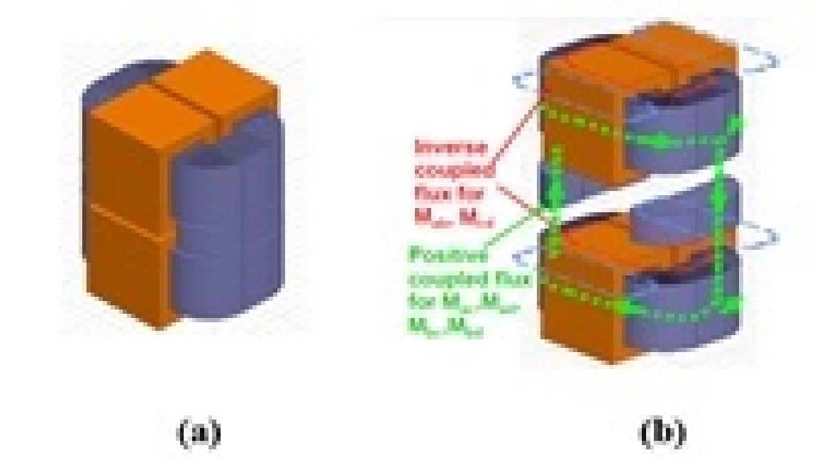
Fig. 2. (a) Integrated structure with tape-wound core (b) Exploded view: Flux path in the coupled inductor.
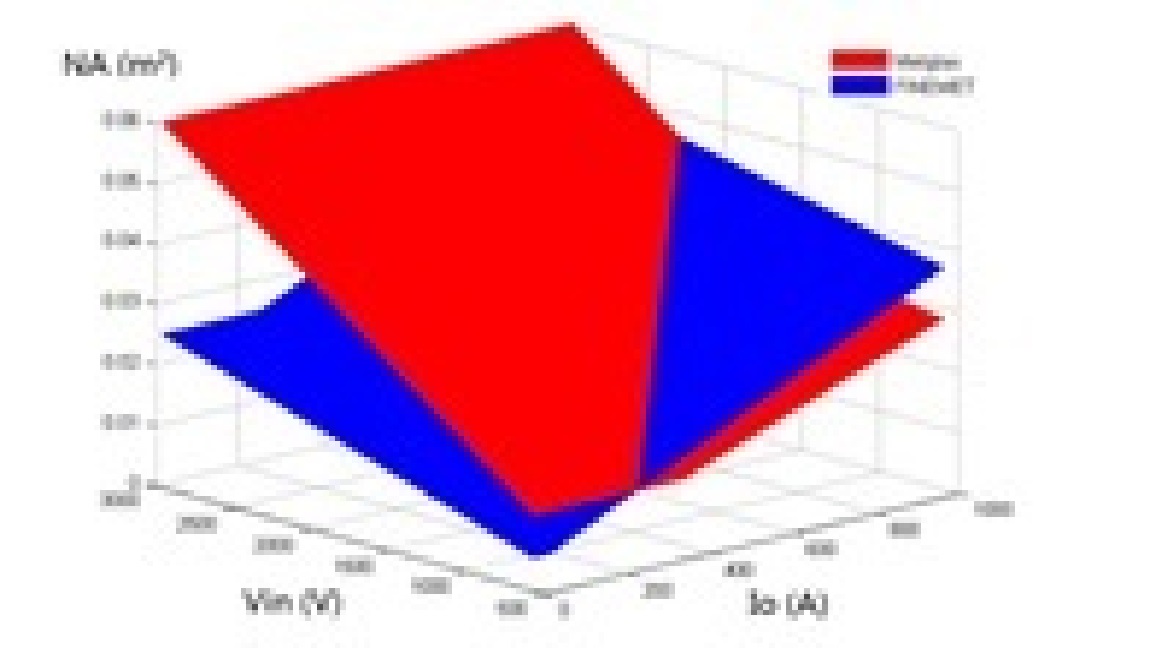
Fig. 3. Comparison of amorphous and nano-crystalline materials.
