


LIBRARY
High-Frequency PCB Winding Transformer Design for On-Board Battery Charger
Year: 2016
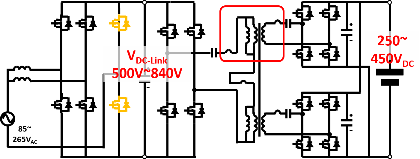
Fig.1. System structure of the proposed two-stage on-board battery charger.
With the proposed variable DC-link voltage, the CLLC resonant converter can always work at its optimized point. In addition, two sets of full-bridge rectifiers are used to handle the high charging current. A PCB winding-based transformer using a split core is proposed so that only a 6-layer PCB is needed to realize a 12:6:6 turns ratio. Also, a novel EI core structure is used to help achieve the desired magnetizing inductance and leakage inductance, as shown in Fig. 2. By using the center post as a leakage path, the leakage inductance and magnetizing inductance can be controlled by changing the gap of the center post and outer post. With leakage integration, both primary-side and secondary-side resonant inductance is realized by the leakage inductance of the transformer. Another benefit of this structure is that most of the leakage flux is confined inside the magnetic material, avoiding additional eddy current loss and EMI issues. A transformer loss model is built to obtain the winding loss and core loss of the proposed transformer. Based on this loss model, a design procedure is provided to optimize the transformer loss.
A 6.6kW 500kHz prototype of the proposed CLLC resonant converter with PCB integrated transformer is shown in Fig. 3. The testing results show that the proposed transformer structure can achieve the required leakage inductance and magnetizing inductance. The prototype can achieve 97.7% efficiency with 350V battery voltage and 6.6kW charging power. The results demonstrate the efficiency of the transformer and verify the proposed design.
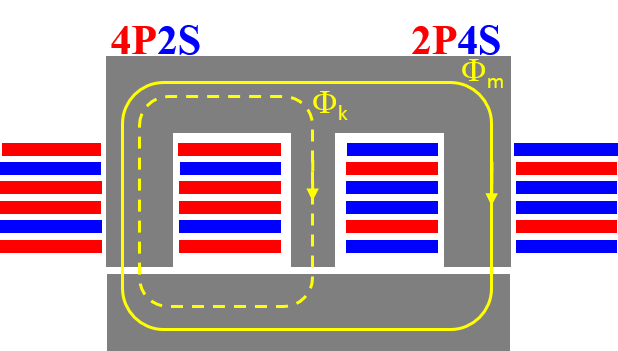
Fig.2. Proposed PCB winding-based transformer with leakage integration
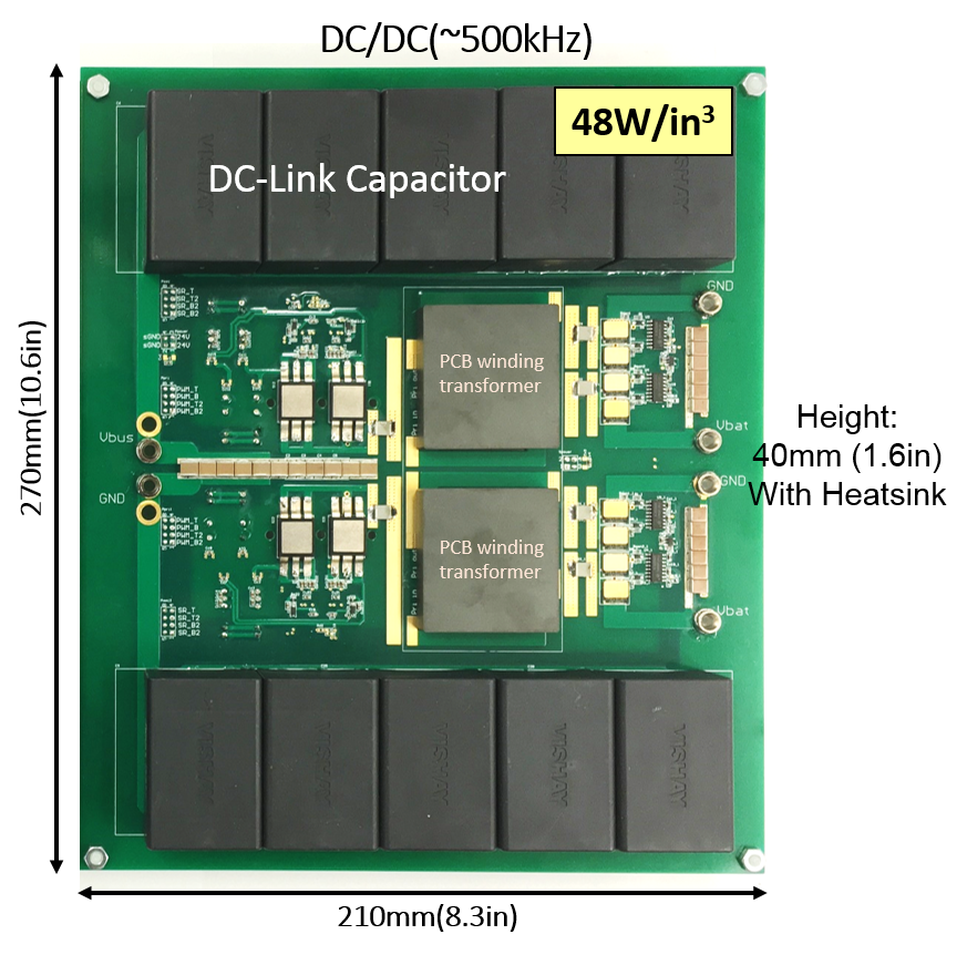
Fig. 3. 6.6kW 500kHz on-board charger second-stage prototype
