


LIBRARY
Passive Component Loss Minimization for Interleaved DC-DC Boost Converters in Electric Vehicle Applications
Year: 2016
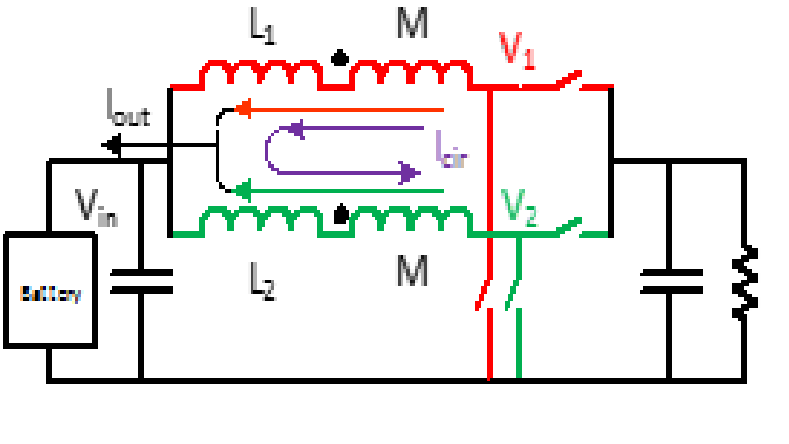
Fig. 1. Interleaved DC-DC converter with coupled inductor
A two phase interleaved DC-DC boost converter with an ideal reverse coupled inductor is shown in Figure 2, where the carrier of converter 2 is phase shifted by 180°. With the phase-shifting of the gate signals, the current ripple of each converter is also phase-shifted, thus causing the total current ripple to be reduced. The inductors are separated as the non-coupled inductor L and ideal coupled inductor M. When the two converters are coupled together, the current through each inductor can be separated as output current Iout and circulating current Icir. With the equivalent circuit shown in the previous section, inductor operation conditions including inductor current waveform and voltage excitation can be predicted by adding different coupled inductance to the circuit. Inductor loss can be calculated with the information of the inductor operation conditions. Figure 2 shows the total inductor loss changes when a different coupled inductor is added to the circuit. From here, it is clear that adding a coupled inductor can reduce the boost inductor loss significantly however, the added coupled inductor will also have additional losses. Increasing the coupled inductance will decrease the boost inductor loss and increase the loss on the coupled inductor, however the effectiveness is reduced when the coupled inductance is large enough and there is an optimal coupled inductance for minimized total inductor loss for interleaved boost DC-DC converters. In order to verify the analysis above, a 1kW interleaved dc-dc boost converter is implemented and tested with different boost and coupled inductors. Figure 3 presents the measured inductor losses for both boost and coupled inductors, which indicate that the total passive component losses is achieved when coupled inductance is 8mH for the experimental prototype.
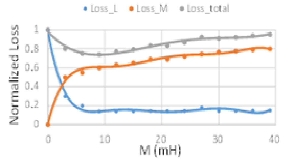
Fig. 2. calculated inductor loss with different coupled inductance M (normalized to total loss without coupled inductor)
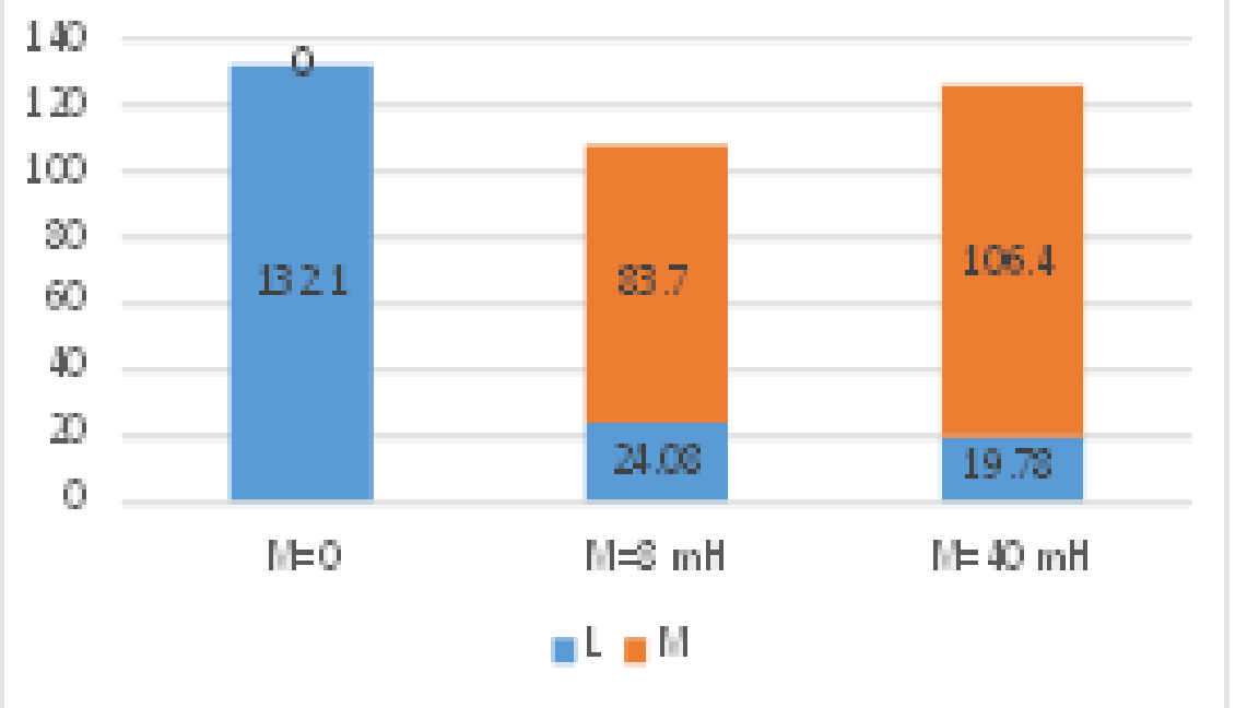
Fig. 3. Passive component loss comparison with different M.
