


LIBRARY
Point-of-Load Inductor with High Swinging and Low Loss at Light Load
Year: 2016
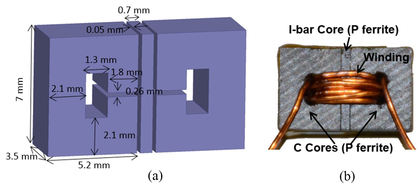
Fig. 1. (a) 3D model and dimensions of (b) 2D-gapped inductor in experiment with N = 8 and winding diameter of 0.46 mm.
In this work, a uniform-gap ferrite inductor is retrofitted with a 2D gap to realize high swinging and low loss at light load without modifying the volume or the dc resistance. A thin gap is placed orthogonally to the existent thick gap to take advantage of the significantly larger cross-sectional area in the orthogonal direction. The thick gap is assumed horizontal and the thin gap vertical in the remainder of the paper. Inductance, core loss, and winding loss are optimized simultaneously to minimize the total loss at light load. The trade-off between inductance swinging and saturation is analyzed to optimize the thickness of the saturable piece. A finite-element simulation is the primary tool to deal with the ac winding loss, bias-dependent and frequency-dependent core loss, and nonlinearity owing to saturation.
If the thin gap is placed in-line (1D) with the thick gap, as is the case for the "stepped gap", an attempt to increase the light-load inductance would cause the core to saturate since an increase of the thin gap's area must be accompanied by a decrease in the thick gap's area. The 2D gap arrangement essentially decouples the two effects by two independent and orthogonal geometrical parameters: the thickness of the I-bar and the cross-sectional area of the thin gap. The thickness can be designed to avoid saturation of the C-cores, whereas the large cross section available in another direction yields a higher light-load inductance.
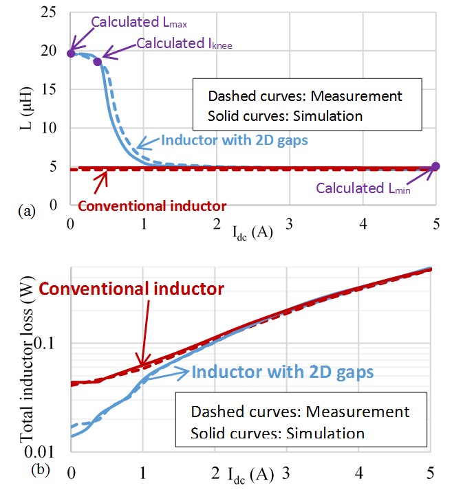
Fig. 2. Measured and simulated (a) inductances and (b) losses for a conventional inductor and an inductor with 2D gaps; calculated Lmax, Lmin, and Iknee are also shown.
