


LIBRARY
Normalized Design Method for Coils in Series-Series Inductive Power Transfer System
Year: 2016

Fig. 1. Topology of series-series inductive power transfer .
However, the designed values of the above mentioned parameters for the IPT coils are not repeatable or optimized for different specifications, e.g. operating frequency and load conditions, so the coil parameters need to be redesigned whenever the specifications are changed. To avoid such a redundant re-design process, normalized parameters, including load quality factor, coil quality factor, and normalized operating frequency, are implemented in the design process of the IPT coils. The normalized parameters are independent of the specifications, so the design results can be used for different specifications. In this paper, a systematic design method is demonstrated for normalized parameters of coils in a series-series IPT system as in Fig. 1. The desired voltage gain, soft-switching of the converter switches, and required coil efficiency are all achieved following this method.
To verify the normalized design method, coils with the dimensions of 250 mm 250 mm and a 100 mm air gap are designed for a 3.3 kW IPT system. The experiment proves that the desired output voltage from 200 V to 400 V is achieved with a corresponding voltage gain from 0.5 to 1. The ZVS of the inverter devices is achieved because the inverter's output current is lagging behind its output voltage. As required, coil efficiency is larger than 97%.
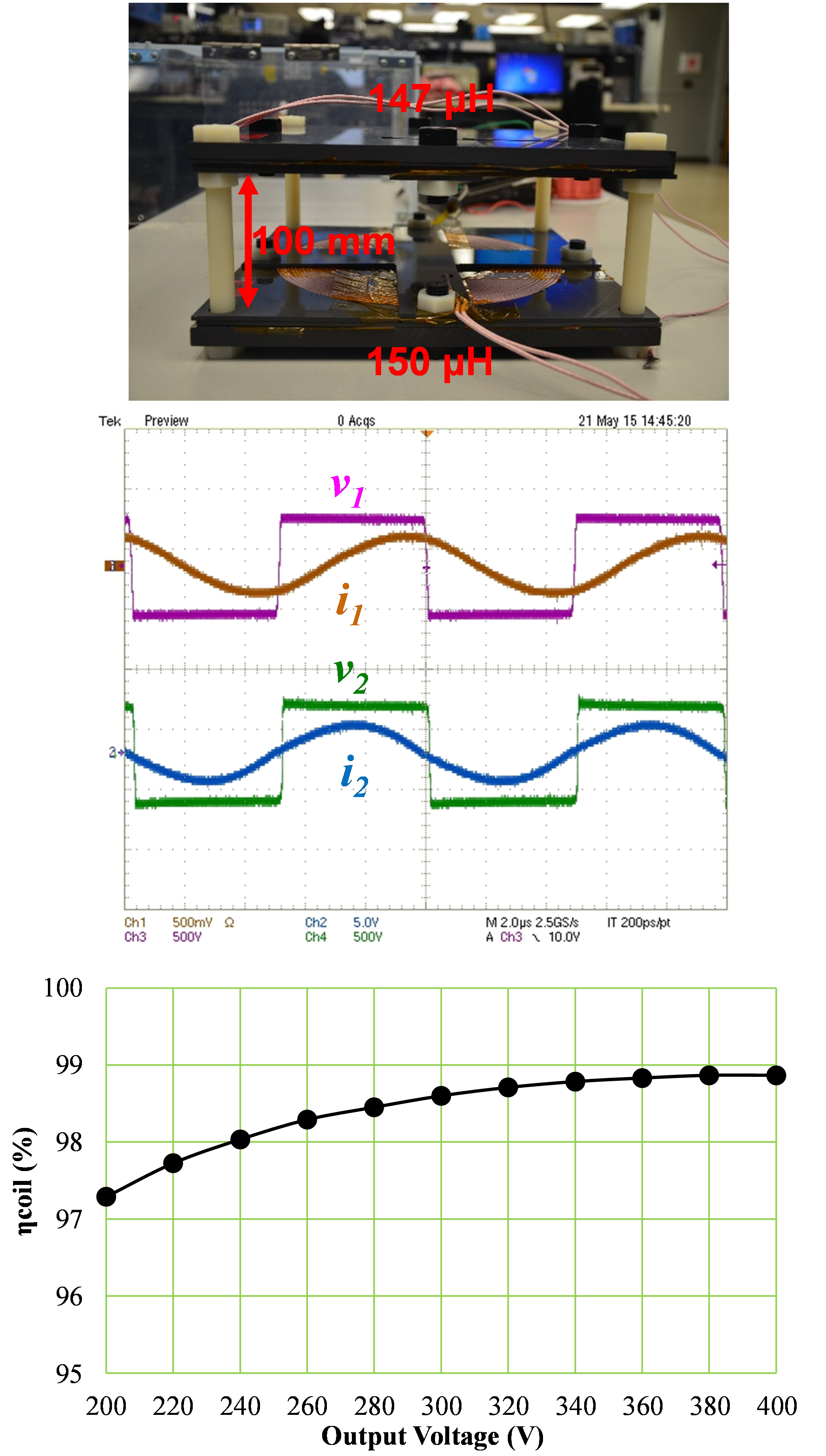
Fig. 2. Coils for experimental verification and its measurement results.
