LIBRARY
Digital Controlled MHz Critical Mode PFC with Simplified On-time Calculation for Minimizing Input Current Distortion

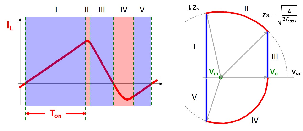
On-time calculation was, previously based on the state-plane trajectory shown in Fig. 1. From Fig. 1, an analytical model of the inductor current is derived to calculate the average inductor current. To achieve a low current THD, the average inductor current needs to follow a sinusoidal shape. By making the average inductor current equal to the sinusoidal reference current, an on-time distribution in line-cycle is derived as a highly non-linear complicated expression. The calculation time is estimated to be more than 3000 CPU cycles of MCU, for 120MHz MCU, which is equivalent to several tens of switching periods at MHz frequency level. This long calculation time makes on-time update slowly and causes a high current THD.
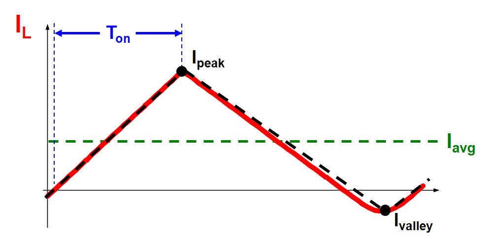
So here, a triangular-shape approximation is made on the switching-cycle inductor current waveform, as the black dash line shown in Fig. 2, since the non-linear part of the waveform only happens during resonance, which is a much shorter time period compared to the switching period. The approximation simplifies the calculation of the average inductor current, which is simply the average of peak current and valley current.
Similarly, by making the average inductor current equal to the sinusoidal reference current, on-time distribution in line-cycle is derived as a very simple expression.
After simplification, the required calculation time is about 30 CPU cycles of MCU, for 120MHz MCU, equivalent to a quarter of the switching period even at MHz high frequency, which demonstrates a more than 100x improvement. As shown in Fig. 3, accuracy is not sacrificed due to the simplification, and what's more, low current THD is achieved.

.jpg)
.jpg)


