LIBRARY
Omnidirectional Wireless Power Transfer for Portable Devices

In this paper, the field direction preference for a portable device is first analyzed. Due to mechanical reasons, a small portable device will drop into the bottom of a charging platform. Since the orientation is very flexible for the small portable device, the omnidirectional field prefers to be in the bottom of the charging platform. On the other hand, only planar devices can lay on their side face. Therefore, a field perpendicular to the surface is preferred for planar devices in side face. Then omnidirectional wireless power transfer platform proposed by Intel and the City University of Hong Kong is analyzed with FEA simulation and a numerical model. Unfortunately, there is no omnidirectional field in the bottom of the two charging platforms.
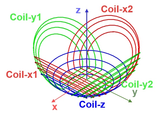
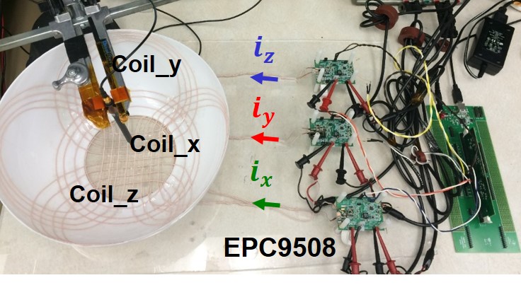
A new transmitter coil structure to achieve an omnidirectional field in the bottom and perpendicular field at side face is proposed, as shown in Fig. 1. With this new coil structure, it is easy to understand that the field is perpendicular to the surface in side face. On the other hand, the omnidirectional field distribution in the bottom of proposed transmitter coil structure can be induced with modulation excitation current. The transmitter coil structure is implemented, as seen in Fig. 2. They are driven by three sets of 6.78MHz LCL resonant converters. The excitation current of these three sets of coils is modulated excitation current. With this system, field distribution in the bottom at different time instants is shown in Fig. 3 by FEA simulation. Also, the omnidirectional field can be measured with a near-field probe in the experiment.


