LIBRARY
Modeling and Analysis for Input Characteristics of Line-Frequency Rectifiers

This paper proposes a new model by using the harmonic balance method. Detailed analysis indicates that input admittance of the line frequency rectifier in high frequency regions acts like a resistor rather than an inductor. The simulations validate the accuracy and effectiveness of the proposed model.
For nonlinear power electronic converters, the definition of impedance makes classical control theory easy to use . This solves many problems and brings lots of convenience, but the simplification of real input characteristics also has some limitations. It has been reported that the output impedance model fails to analyze the multi-phase voltage regulator's characteristics when there is a load transient whose frequency is beyond switching frequency and power electronic based systems' interactions in switching frequency range.
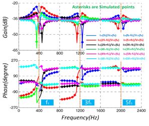
Fig.1 shows the simulated input current and voltage waveforms with perturbations. Simulation results coincide with theoretical values, which validates the accuracy of the proposed model.
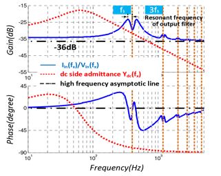
The describing function (input admittance) iin(fx)/vin fx can be obtaines as shown in Fig. 2. The figure shows that the highest gains appear around line frequency and the distance between peak points and line frequency is resonant frequency of output low pass filter.


