


LIBRARY
A Novel PCB Winding Transformer with Controllable Leakage Integration for a 6.6kW 500kHz High Efficiency High Density Bi-Directional On Board Charger
Year: 2017 | Author: Bin Li | Paper: D4.14
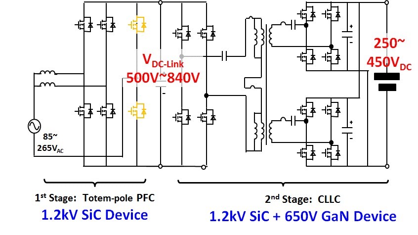
Fig. 1. System structure of the proposed two stage on board battery charger.
A two stage on-board charger structure with variable dc-link voltage is proposed as shown in Fig. 1, using bridgeless totem-pole PFC as the first stage and the CLLC resonant converter as the second stage. Due to the variable dc-link operation, the gain range requirement of the CLLC resonant converter is greatly reduced. For the output side, two sets of full bridge rectifiers are used to handle the high charging current. A PCB winding based transformer based on a split core is proposed so that only a 6-layer PCB is needed to realize a 12:6:6 turns ratio. Also, a novel EI core structure is used to help achieve the desired magnetizing inductance and leakage inductance, as shown in Fig. 2. By using the center post as the leakage path, leakage inductance and magnetizing inductance can be controlled by changing the gap of the center and outer posts. With leakage integration, both the primary and secondary side resonant inductance are realized by the leakage inductance of the transformer. A transformer reluctance model is built to help achieve the target inductance. Also, a loss model based on 2D FEA simulation and rectangular extension of Steinmetz's equation is built to get the winding loss and core loss of the proposed transformer. Based on this loss model, a design procedure is provided to optimize the transformer loss.
A 6.6kW 500kHz prototype of the proposed CLLC resonant converter with PCB integrated transformer is built. The testing results show that the proposed transformer structure can achieve the required leakage inductance and magnetizing inductance. The prototype can achieve 97.8% efficiency at 350V battery voltage with 130W/in3 power density.
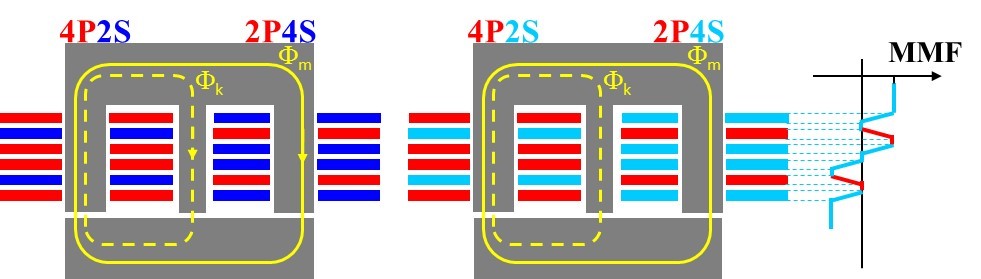
Fig. 2. Proposed PCB winding based transformer with leakage integration.
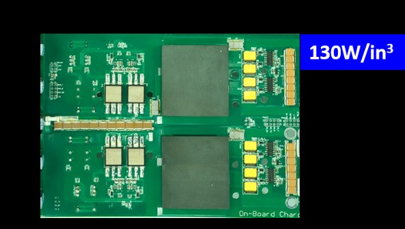
Fig. 3. 6.6kW 500kHz on board charger second stage prototype.
