LIBRARY
Analysis of D-Q Small-Signal Impedance of Grid-Tied Inverters

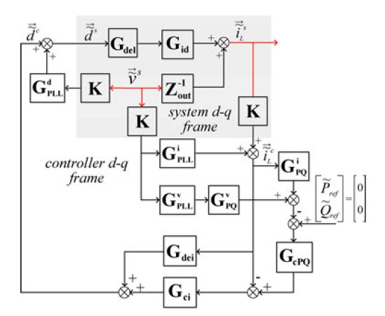
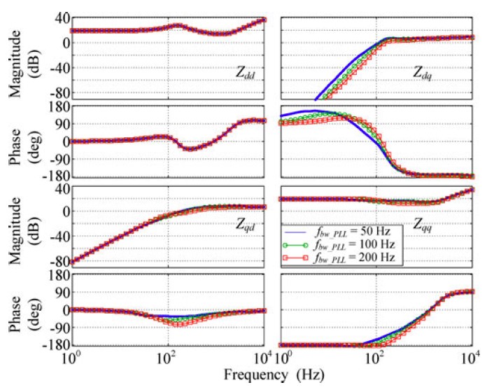
This paper presents an analysis of the grid-tied inverter small signal impedance in a d-q frame under different control strategies. Influences of PLL, and current and power feedback control to the inverter impedance are discussed. Some important features of inverter impedance are discussed. These features indicate that a grid-tied inverter working as a current source could destabilize the system due to the negative incremental resistor of Zqq. This negative incremental resistor behavior is a result of PLL and current injection. Increasing the PLL bandwidth extends the frequency range of this behavior, and increases in the inverter power level decreases the absolute value of the resistor. A brief simulation example shows that under weak grid conditions, a small increase of the PLL bandwidth can lead the system to unstable conditions. The example also shows how the proposed model can be used to predict such instability. Hardware measurements verify the proposed model. The model gives insight into the grid-tied inverter's behavior in the grid. Harmonic resonance and instability issues reported in the literature can be analyzed using the characterized impedance model.


