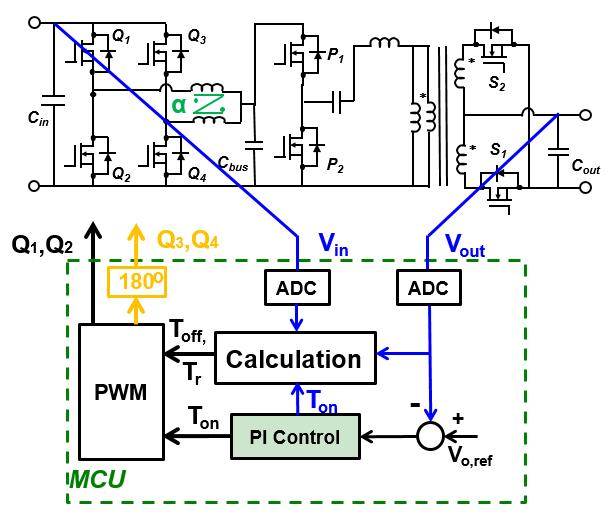
Fig. 1. Proposed two-stage dc-dc module with digital controller.
It is currently difficult to improve upon the efficiency and power density of silicon (Si)-based power converters, since Si-based semiconductor devices have approached their theoretical performance limit. Further efforts are being made toward developing high-performing gallium-nitride (GaN)-based converters instead, because of their superior characteristics including small on-resistance, almost no turn-off loss, and a small gate charge. This paper develops a GaN-based dc-dc converter for railway applications. This rail-grade converter can provide isolated dc power in the transportation industry for electronics such as LED displays, audio amplifiers, safety monitors, lighting, and communications systems. A two-stage configuration is proposed as shown in Fig. 1. The first stage is a two-phase interleaved critical mode buck converter, which is needed to transform the wide input (64 V-160 V) to a constant 48 V bus voltage. The second stage, a 2 MHz LLC converter (DCX), is used for 4824 V conversion. Due to the voltage demand, both high-voltage devices and low-voltage devices are required. Even though there are no 300 V GaN devices for the buck converter, the 650 V GaN device is still much better than the 300 V silicon-carbide device. Finally, G66506T and EPC2031 are used for the first and second stage respectively.
In this proposed system, the two-phase interleaved buck converter is used for voltage regulation. Under critical conduction mode, the voltage regulation must change the on-time of the main switch and the frequency simultaneously. Meanwhile, the negative coupled inductors are used to help magnetic integration. This negative coupling affects the static inductance and the resonant inductance, i.e, resonant with junction capacitance for zero voltage switching (ZVS). With the selected negative coupling coefficient (-0.7), the input voltage losing ZVS is from 68 V to 96 V. To solve this issue, the synchronous rectifier off-time is purposely delayed to inject more energy for ZVS operation. All the mentioned functions (voltage regulation and ZVS extension) are finally implemented through a 60 MHz microcontroller unit (TMS320F28027).
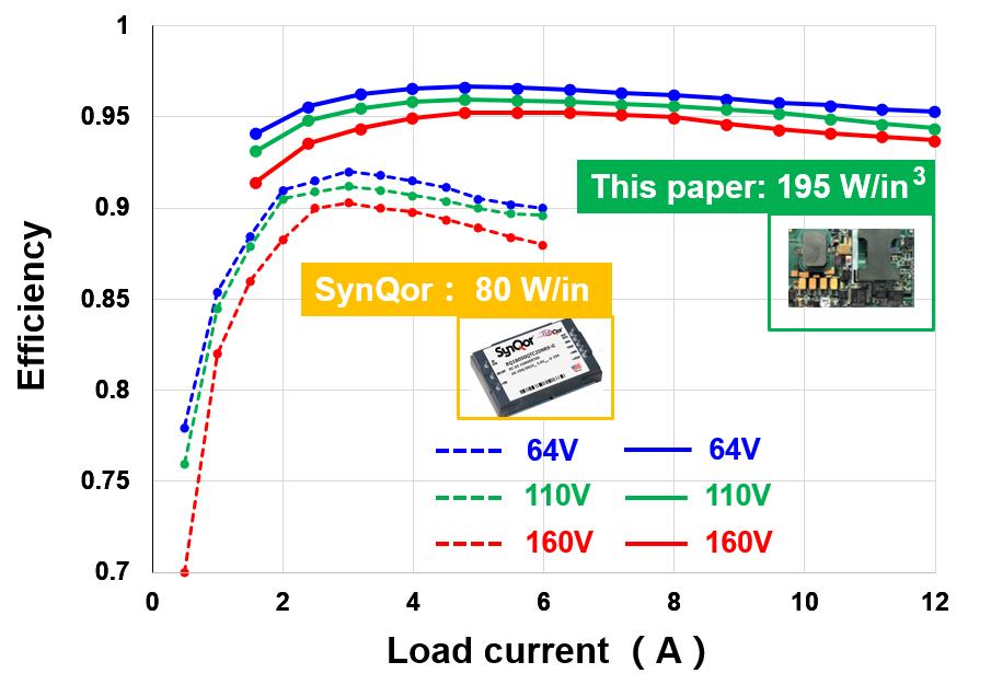
A 300 kW rail-grade converter is built as shown in Fig. 2. Its footprint is a standard quarter brick (2.3 inch ×1.45 inch), which is exactly the same as that of the benchmark system (SynQor's module). This standalone system, as a commercial product, includes power stages, a digital controller, an auxiliary power supply, protection circuits, and power management bus (PMBus) chips. The measured peak efficiency is 95.8 percent with a power density of 195 W/in
3.

Fig. 2. Comparison between the proposed module and SynQors module.


