


LIBRARY
Modeling Resonant Converter in a Rotating Polar Coordinate
Year: 2018 | Author: Yi-Hsun Hsieh | Paper: D2.5
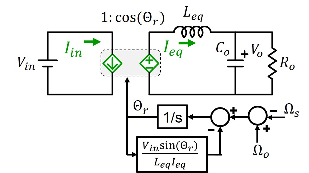
Fig. 1. Proposed average model of a series resonant converter (SRC).
Recently, Y. Hsieh modeled resonant converters in a rotating coordinate. Using a rotating coordinate transformation, the equilibrium state of the operating point on the state plane is readily defined. Therefore, the standard modeling process, from average, perturbation, to linearization can be easily employed to model resonant converters. The resulting third-order equivalent circuit model is accurate up to switching frequency, however, the physical meaning of the mutual coupling remains vague.
In this paper, modeling based on a rotating polar coordinate is proposed. The resulting equivalent circuit model is shown in Fig. 1. The entire resonant tank, including the inductor and capacitor, is regarded as an energy storage element, and modeled as an inductor. The internal energy feedback within the resonant tank is modeled correspondingly as current feedback. The model clearly shows the resonant converter is regulated by ωs-ωo.
The small-signal model is shown in Fig. 2. When ωs operates away from ωo, the bandwidth of the current loop is found to be the beat frequency. Moreover, the additional phase delay from the low-pass filter explains the double pole locating at the beat frequency. The resonant tank can be regarded as a current source since the tank energy is regulated. Consequently, there is a single pole from Ro and Co. When ωs operates around ωo, the current feedback is weak, and therefore there is a double pole from the resonance between the resonant tank and Co. The low-pass filter remains as a high frequency single pole.
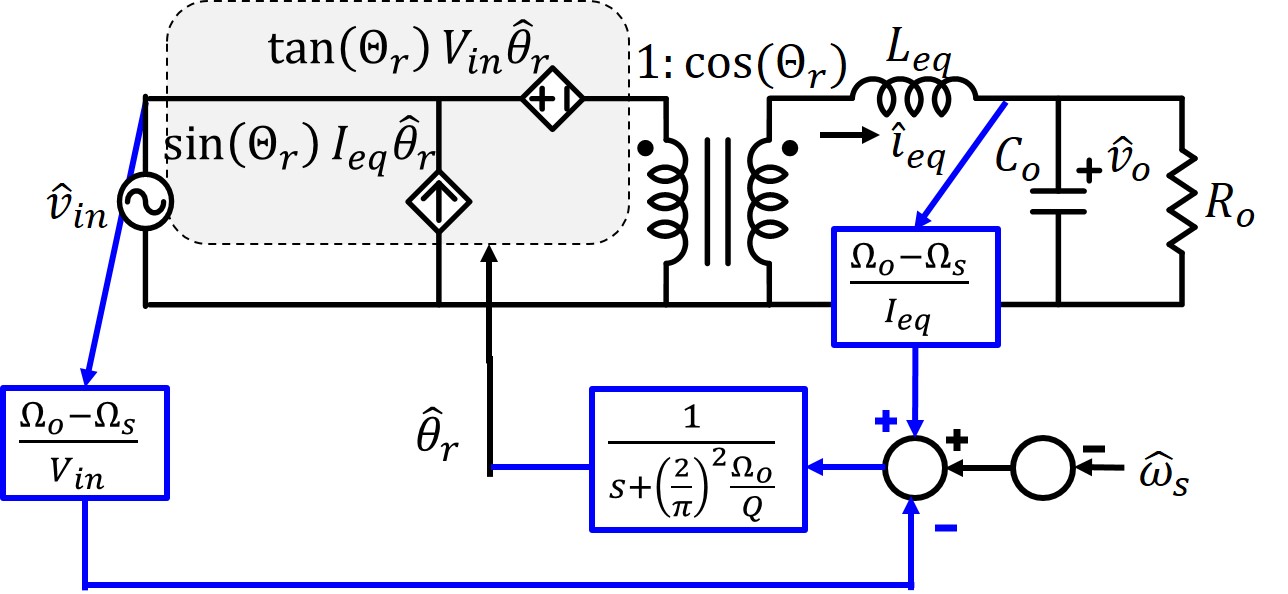
Fig. 2. Proposed small-signal model of an SRC.
