


LIBRARY
A New Inverse Charge Constant On-Time (IQCOT) Control for Noise Performance Improvement in Multiphase Operation
Year: 2018 | Author: Syed Bari | Paper: D2.10a
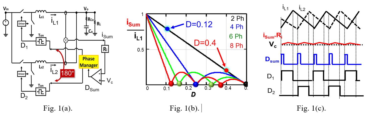
Fig. 1. (a) Conventional COTCM control structure. Fig. 1. (b) Ripple-cancellation effect. Fig. 1. (c) Small Isum ripple at D ≈ 0.4.
This paper proposes a new COTCM control method based on the inverse charge control concept (IQCOT control). In Fig. 4, a two-phase COTCM control with the proposed structure is shown. In this control, unlike conventional COTCM, Vc-Isum is used to charge a capacitor and in every cycle, the cap voltage (Vramp) is compared with a VTH to generate the duty cycle for control. The advantage of the proposed IQCOT control is that, as it is not a ripple-based control, when the duty cycle is approaching the ripple cancellation point, and the inductor current ripple becomes very small, there is no noise impact, since modulation depends on the Vramp signal, which is still very large. Furthermore, at the ripple cancellation point, when the ripple is zero, the converter can still operate normally, as Vramp can still be generated by the voltage difference between Vc and IL × Ri. This is shown in Fig. 5, where for four phases, the converter is operating at the ripple cancellation point (at D = 0.25), and the ripple current summation ILsum is zero. But fsw is determined by the Vramp signal, which is 2V in this case. Fig 6 shows the test results for the proposed control. As illustrated, in two-phase operation with D = 0.5, Isum is almost negligible.
