LIBRARY
Phase Current Sensor and Short Circuit Protection Based on PCB-Embedded Rogowski Coils Integrated in the Gate Driver of a 1.2 kV 300 A SiC MOSFET Module

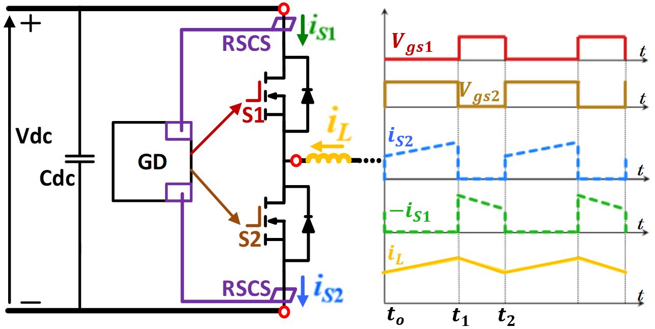
Architecture for this gate driver includes an RSCS for the top and bottom devices on the controller (common) ground and digital reconstruction of the phase current. In order to subtract two-current information in some sort of digital signal processor, two analog-to-digital converters are required. A field-programmable gate array is employed for digital subtraction and turning off the RSCS when the corresponding switch is not conducting. A digital-to-analog converter is necessary to convert phase current information back to analog in order to emulate commercial current measurement, perform a comparison, and send information to the controller for control purposes.
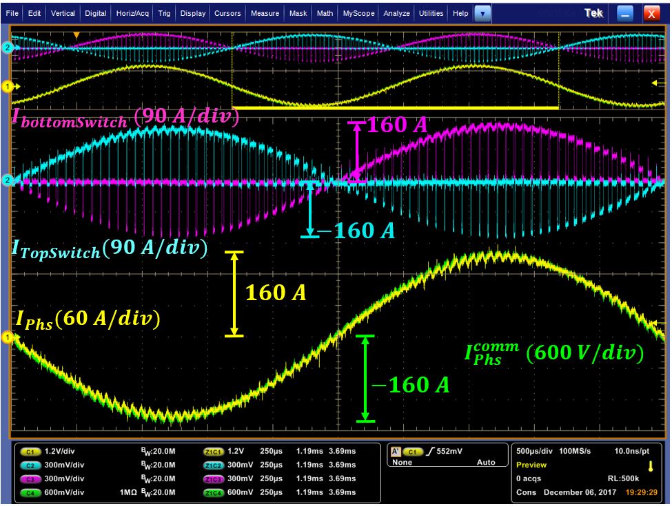
Fig. 2 shows the reconstructed sinusoidal current from one of the phases of the inverter, together with the switches current of the corresponding phase. It is clear that the reconstructed phase current waveform (yellow) is the result of subtracting the top switch current (cyan) from the bottom switch current (purple). Comparison with the commercial measurement (green) can also be seen in Fig. 2. The reconstructed phase current appropriately follows the commercial measurement in both amplitude and phase with a consistent delay of 1.6 µ. Tests are performed with the low gate source external resistance in order to push transient speed and reduce switching losses. dV/dt was 15 V/ns. In this severe noise environment and from switch currents illustrated in Fig. 2., it is shown that there are no shoot-through events caused by the Miller effect or induced signal malfunction. Furthermore, chosen components that participate in phase current reconstruction cope well with the common mode noise created by the dV/dt, and successfully reconstruct the current.


