LIBRARY
Design and Control of Modular Motor Drives

Optimizing performance while complying with the form factor and other constraints is key to designing modular converters. To unveil the potential of the modules, nominal power is selected as the ultimate objective function and will be maximized. An optimum design is found through detailed topology evaluation, loss-size modeling of components, and a multilevel, multi-objective optimization. A nominal power of 5 kVA is estimated to be the maximum rating, and two modules are constructed accordingly. Each module achieves 99.2 percent full load efficiency and 80 W/inch3 power density. No active cooling is required due to its extreme efficiency.
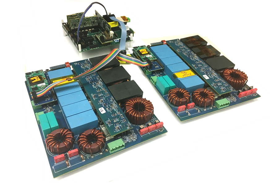
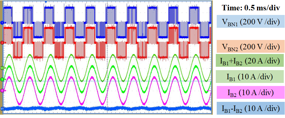
A control system consisting of a central controller and multiple local controllers is proposed and tested. Local controllers synchronize to, and receive commands from, the central controller, and close the current (torque) loop locally. The central controller closes the voltage (speed) loop, and broadcasts current references to the converter modules. Though there is no communication between converter modules, they synchronize well, and no low frequency circulating current is observed in either transient or steady state tests (test setup shown in Fig. 1 and transient waveforms shown in Fig. 2). Signal integrity issues brought up by paralleling converters will also be discussed.
Lastly, this paper opens a discussion on the optimum form factor for modular converters. A modular converter is designed with doubled height, the same footprint area, and doubled loss budget, and is compared with the original design. Results show a 10 percent increase in maximized nominal power. This increase indicates the influence of system constraints on overall performance, and suggests a need for research on the optimization of system level parameters.


