LIBRARY
Low-Frequency Common-Mode Voltage Control for Systems Interconnected With Power Converters

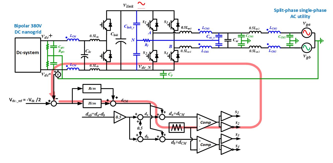
In this paper, a CM duty cycle injection method was proposed to actively control the dc bus to ground voltage. As a result, the dc bus voltage is symmetrical, and the low frequency voltage ripple is suppressed. The operation range of the proposed method was identified and proved to be easily met. The impact from the different voltage level and asymmetrical ac grounding was analyzed. The complete CM circuit model was derived and verified by hardware, based on the design of the closed loop controller. The experimental result verifies the control method in steady state and transient modes. The trade-off was clarified. The control method was also generalized to a three-phase ac scenario.
To verify the proposed low-frequency CM voltage control method, a 10 kW bidirectional ac-dc converter was built. As shown in Fig. 2 (a), after enabling the control loop, the dc bus voltage is adjusted to be symmetrical to the ground. The low-frequency ripple is also suppressed. Fig. 2 (b) and (c) show the steady state ac voltage, ac current, and positive and negative dc bus voltage, with and without the CM voltage control. ??


