LIBRARY
Optimal Design of Planar Magnetic Components for A Two-Stage Rail Grade DC-DC Converter

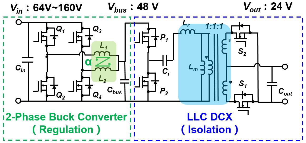
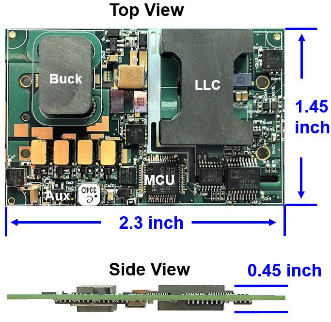
This paper focuses on the design and optimization of planar magnetic components (i.e., the inductors and transformer in Fig. 1), with six-layer printed circuit board (PCB) windings. The benefits of negative coupled inductors for the buck converter are discussed. It is helpful to reduce the conduction losses under CRM and integrate the inductors. In order to reduce the inductor loss, the planar coupled inductors with winding interleaving are optimized based on finite element simulation. Two inductors are easy to couple through a customized EI core, and a same air gap design is proposed to improve the manufacturability. Similarly, the planar transformer of the LLC DCX is optimized with a customized EI core based on an analytical model. All the devices—magnetic components, digital controller, auxiliary power supply, sensing and communication chips—are integrated on a single quarter brick PCB in order to build a standalone dc-dc module. Finally, a standalone prototype converter is built with the proposed planar coupled inductors and transformer in a quarter brick form. The measured peak efficiency can reach 95.8 percent, with power density at 195 W/in3.


