LIBRARY
High Efficiency Two-stage 48 V Bus Converter with Integrated Magnetics

In this work, a two-stage solution with integrated magnetics is proposed for 48 V/12 V—1 kW bus converters which can provide both regulation and isolation capabilities. The first stage is a two-phase buck converter to achieve the required regulation capabilities. The second stage is a fixed-frequency LLC converter, utilizing an integrated matrix transformer for the isolation. The current practice for dc-dc bus converters is to operate at low switching frequencies (100—200 kHz ), with power density below 400 W/in3. For higher power density, this converter will operate at a higher frequency than standard industry practice. An LLC converter is most often used for high-frequency operations, due to its soft switching properties for primary and secondary devices. It can also achieve higher efficiency and higher power density. In high-output current and low-voltage applications, the matrix transformer has proven to have good performance, since it distributes the secondary current among multiple outputs in order to reduce the total conduction loss.
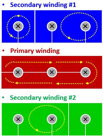
To deliver a 1 kW output power, three elemental matrix transformers are connected in parallel from secondary windings, and in series from primary windings, as shown in Fig. 1. The three elemental transformer cores are integrated into one. The proposed printed circuit board (PCB) winding arrangement is shown in Fig.2. The secondary windings, which share the same connections, are overlapped to cancel the leakage flux in the transformer, and achieve smaller winding loss. A prototye is developed for the proposed converter achieving a power density of 670 W/in3, with estimated efficiency more than 97 percent higher than all available industry practices.


