LIBRARY
Field Attenuation around Inductive-Power-Transfer Coils with Dual-Side-Controlled Converters

Finite element simulation with Ansys Maxwell was implemented to verify the effectiveness of field attenuation by controlling the phases of windings' currents. An exemplary set of circular coils with 250 mm diameter and 100 mm gap was used to transfer 3.3 kW power for a series-series IPT system. Compared to the conventional case when the phase difference is 90° between currents of the transmitter and receiver, stray magnetic field was reduced by up to 30 percent and 40 percent with 50° and 40° of phase difference, respectively.
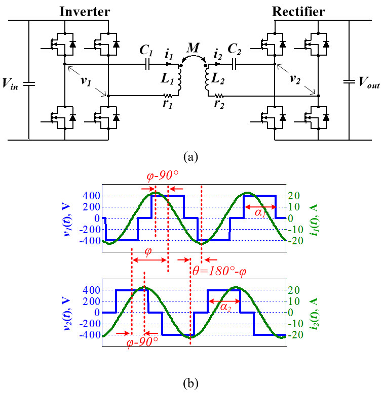
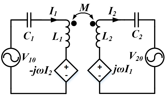
In the inductive power transfer systems to charge electric vehicles, the phases of windings' currents can be controlled to attenuate the stray magnetic field around the coils. The diagrams of phasors for the currents and fields are used for the analysis. The dual-side-controlled converter is applied to change the magnitudes and phases of the currents, in which the bridge legs with MOSFETs are used for both the inverter on the transmitter side and the rectifier on the receiver side. The magnitudes of the currents are controlled by the pulse widths of the inverters and rectifier'as voltages, while the currents' phases of winding currents are controlled by the voltages' phases. Compared to the conventional series-series IPT with 90° phase difference between the currents, the stray magnetic field is attenuated by up to 30 perecent and 40 percent when the phase differences are 50° and 40°, respectively, with the same amount of power transferred.


