


LIBRARY
A Small-Signal Model of the Sigma Converter with Current Mode Control
Year: 2018 | Author: Virginia Li | Paper: T2.1
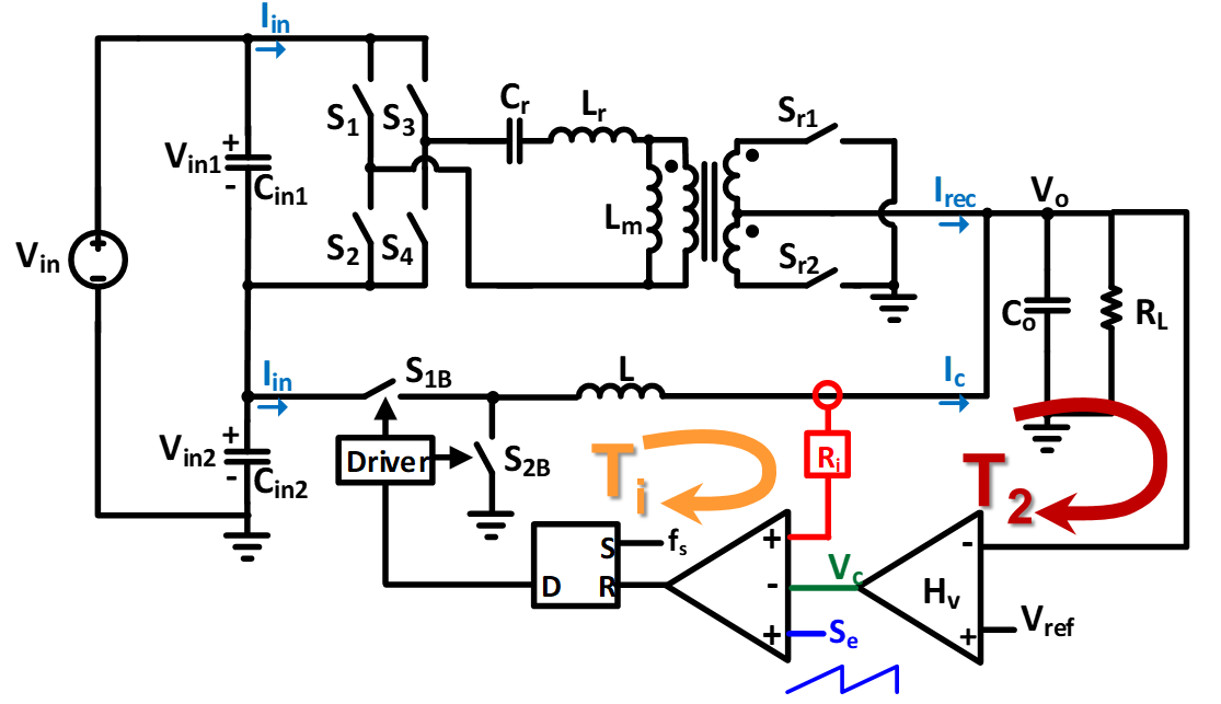
Fig. 1. Sigma converter with peak current mode control.
The sigma converter is a quasi-parallel converter consisting of a dc-dc transformer, and a dc-dc converter with the inputs connected in series and the outputs connected in parallel. For the 48 V to 1 V VRM solution, a fixed-frequency LLC converter operating at resonant frequency and a peak current mode (PCM) buck converter are used as an example. The circuit representation of the PCM sigma converter is shown in Fig. 1. For simplicity, only the current of the buck converter is sensed and used to control the buck converter.
Given this setup, the small-signal model of the PCM sigma can be derived by connecting the small-signal models of the LLC and PCM buck converters in the sigma configuration. In order to directly use the small-signal models of the LLC and PCM buck converters in the sigma configuration, the input and output behaviors of each converter must be retained by the models, due to the series connection of the converters on the input side. For other types of current-mode controlled sigma converters, the same derivation methodology can be used. Examining the small-signal model of the PCM sigma, when only the current loop (Ti) of the buck converter is closed, the system is unstable. This behavior is similar to a converter with a constant power load. The system can be stabilized by closing the (T2) loop and designing the compensator to meet the Nyquist stability criterion. For VRM applications, where an adaptive voltage positioning technique is employed, a constant-gain compensator is sufficient to stabilize the system.
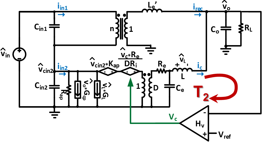
Fig. 2. Small-signal model of the sigma converter with peak current mode control.
