


LIBRARY
Coil and Circuit Design of Omnidirectional Wireless Power Transfer System for Portable Device Application
Year: 2018 | Author: Junjie Feng | Paper: T3.2
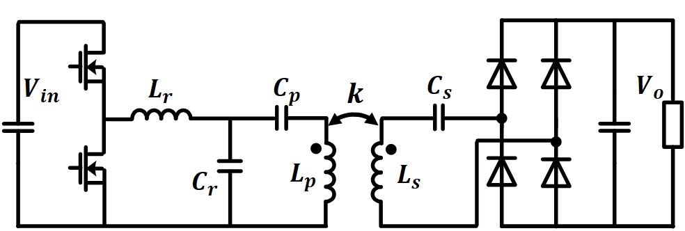
Fig. 1. LCCL-LC Resonant Converter
The large coupling coefficient between the transmitter coil and the receiver coil is the key to achieve a high-efficiency operation in wireless power transfer. Due to flexible receiver positioning, it is a significant challenge to design a transmitter coil that achieves large coupling with a receiver coil for different positioning. In this paper, the coupling coefficient calculation model is built, and an appropriate coil radius range is selected, to achieve large coupling for different receiver positioning.
A high coil quality factor is another key aspect to achieve a high-efficiency operation. A coil quality factor calculation model was built to evaluate the impact of the number of coil turns, and the interval between the different turns, on the coil quality factor. According to the calculation model, the interval between different turns should be small enough to avoid proximity effect loss and achieve a large coil quality factor. In addition, the coil quality factor increases with the number of coil turns, and an appropriate number of turns was selected to achieve a diminishing return effect.
With the designed transmitter coil and receiver coil, Lp and Ls are determined in the LCCL-LC resonant tank. There are only four design parameters (Lr, Cr, Cp, Cs) left in the design process to consider. Inductor Lr is related to the output voltage gain and is determined to have the desired output voltage range for the different coupling cases. The switching frequency in our system is set at 6.78 MHz to follow the airfuel standard. Cs and Cr are designed to resonate with Ls and Lr at 6.78 MHz. Finally, the Cp value was determined to get the required turnoff current to discharge the junction capacitor of the device in the deadtime period and achieve ZVS.
With this proposed design process, a wireless power transfer system with an LCCL-LC resonant converter was built as shown in Fig. 2.
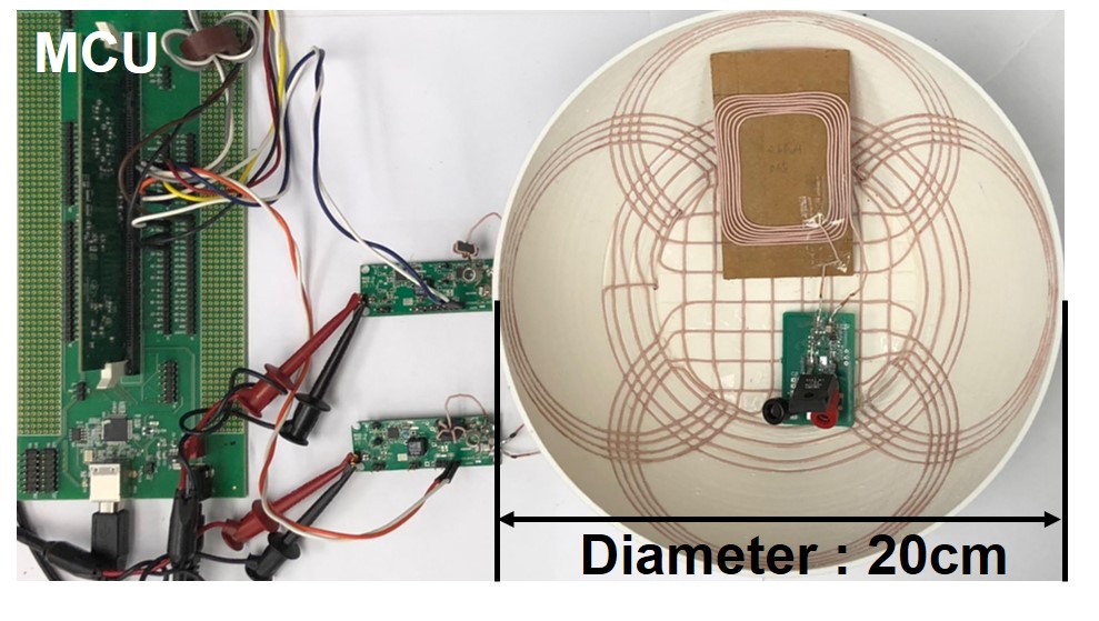
Fig. 2. Omnidirectional wireless power transfer system experiment setup.
