


LIBRARY
EMI Evaluation and Filter Design of a SiC-Based UPS System
Year: 2018 | Author: Jianghui Yu | Paper: T5.1
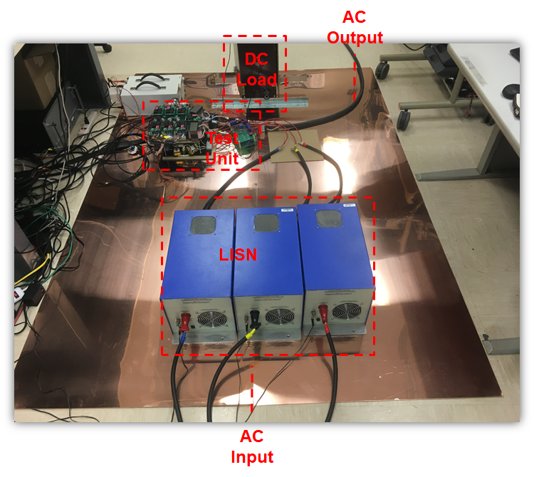
Fig. 1. Conducted EMI emission test environment for UPS systems.
The UPS systems must generate low disturbances so that they will not adversely affect the operation of other parts of the system. The UPS system under evaluation in this study is a static UPS with online configuration. A specific EMI test environment is established to measure the conducted EMI emission. A 1.8 m * 2.4 m copper plane is used as the ground plane. The UPS system under test is placed on the copper plane with 0.5 m distance to the closest boundary. The ac input power port and the ac output power port are on opposite sides of the copper plane, and are connected to the three-phase ac power supply and the three-phase resistive loads, respectively. A resistive load bank is placed on the copper plane to serve as the load during battery charging. Three line-impedance-stabilization-network (LISN) units are located at the ac input power port to measure the disturbance voltages of the main terminal.
First, different EMI profiles under different operation modes are investigated. The disturbance voltage at the ac input port is measured while the UPS system is in normal operation, and then again during charging operation. The disturbance voltage during charging operation has a higher magnitude, of 1 MHz to 30 MHz. The main reason for this magnitude is that the dc-dc charging stage generates common mode (CM) voltage during operation and adds to the total EMI noise. The EMI profile is also affected by the control methods utilized, as will be shown in the final paper.
For a given UPS system, the filters should be designed based on the worst EMI emission in terms of operation modes, but the best EMI emission terms of control methods. A three-phase CM filter and a three-phase DM filter are designed. The attenuated disturbance voltage meet the limits required by the IEC 62040-2 standard, as shown in Fig. 2.
The charging mode introduces additional an disturbance from 1 MHz to 30 MHz compared to the normal operation. A reduced EMI pulse width modulation method for the rectifier and inverter stage and the synchronized dc-dc stage operation are able to reduce the disturbance. The designed EMI filters effectively attenuates the disturbance to meet the limits.
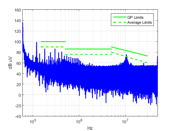
Fig. 2. Attenuated disturbance voltage of phase A.
