


LIBRARY
Three Terminal Common-Mode EMI Modeling and EMI Mitigation Strategy for Full SiC UPS
Year: 2018 | Author: Sungjae Ohn | Paper: T5.4
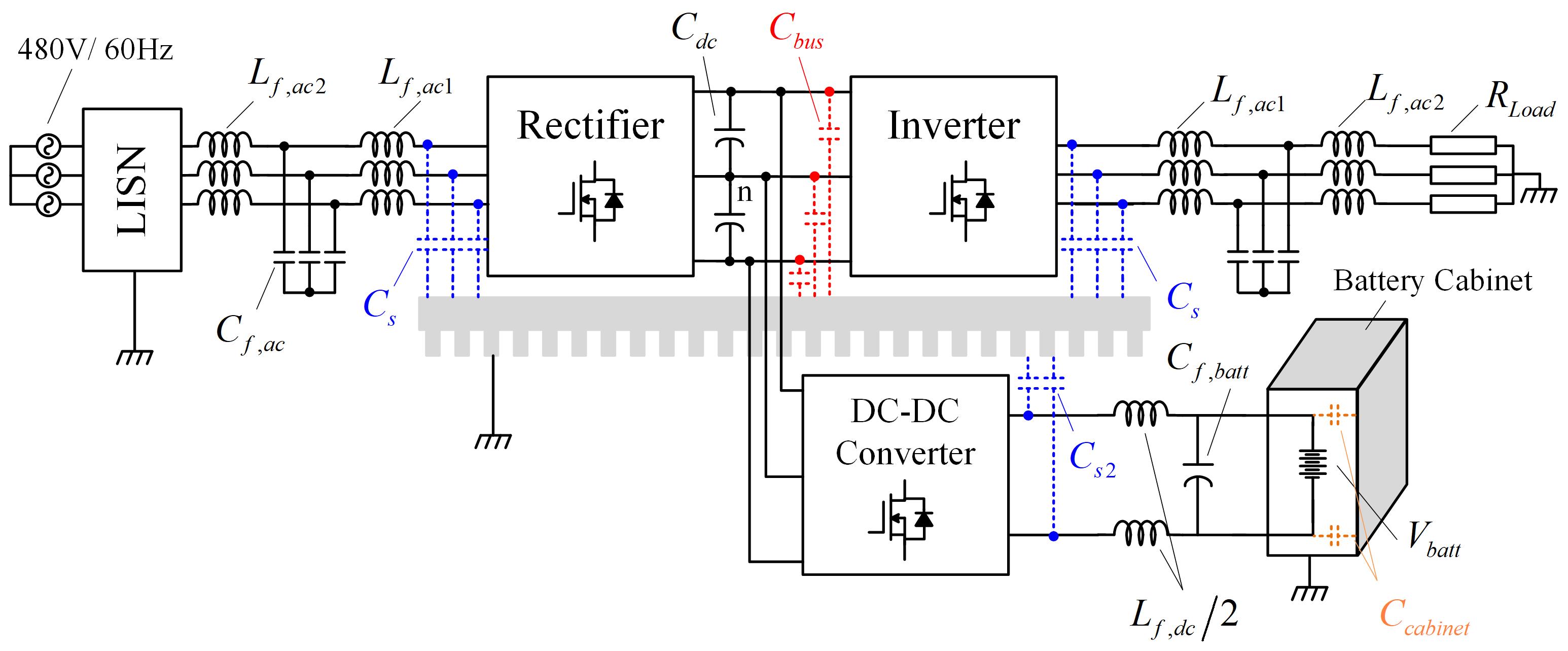
Wide bandgap devices have increasingly received attention from the industry due to their superior performance over silicon-based insulated-gate bipolar transistors (IGBT). The uninterruptible power supply (UPS), as shown in Fig. 1 is one of the application in which the superior loss characteristics of WBG devices can greatly benefit system performance. On the other hand, high dV/dt and di/dt of silicon-carbide (SiC) devices and increased switching frequencies raises electromagnetic interference (EMI) issues. Furtherore, a UPS has several modes of operation depending on combination of rectifier, inverter, and battery charger are involved in the power transfer. Conductive noise should be limited to meet the industry standards even in the worst case. However, there has been no research to clearly explain the impact of dc-dc converter operation on common-mode (CM) EMI combined with an ac-ac stage.
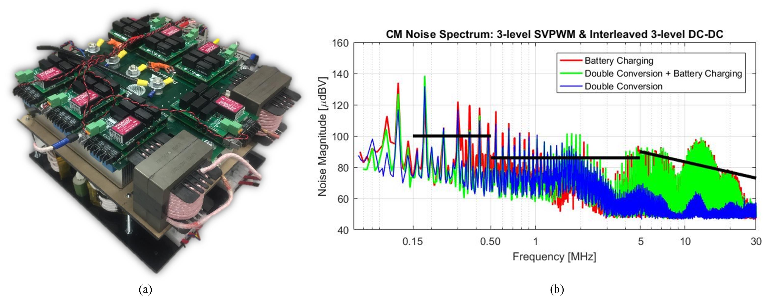
This paper investigates EMI mitigation strategy for full SiC UPS. First, a three-terminal CM EMI model for a UPS with an active battery charger is developed. The model reveals that the dc-dc stage deteriorates output CM EMI via additional noise generation and multiple resonances with the parasitics of the battery cabinet. Second, different topologies and pulse width moudlation (PWM) schemes have been compared to determine the best solution for noise mitigation. Special focus has been given to dc-dc stage topologies and PWM schemes. A 20 kW full SiC UPS prototype has been built to verify the model and mitigation strategy, as shown in Fig. 2 (a). The results show that there is a large increase on CM noise when dc-dc converter operates, as shown in Fig. 2 (b). Experimental results illustrate that selecting the dc-dc converter topology and PWM scheme plays a critical rol in EMI mitigation.
With the proposed combination, CM EMI has been reduced by 14 dB over a wide frequency reange.
Fig. 1. Structure of uninterruptible power supply.
Fig. 2. (a) 20 kW full SiC UPS prototype, and (b) CM EMI spectrum depending on mode of operation.
