


LIBRARY
Beat Frequency Oscillation Analysis for Parallel DC-DC Converters Based on Crossed-Frequency Output Impedance Matrix Model
Year: 2018 | Author: Xiaolong Yue | Paper: NP
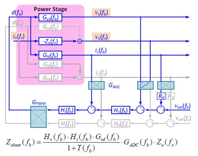
Fig. 1 Small-signal model to derive high-frequency characteristics
In this paper, a crossed-frequency output impedance matrix model is proposed to describe the output terminal frequency characteristics of a dc-dc converter around its switching frequency range. Next, a high-frequency equivalent circuit model is developed to predict the beat frequency oscillation phenomenon introduced by the interaction between two parallel dc-dc converters with different switching frequencies.
The dc-dc stage of the energy control center converter in a dc nanogrid is selected to demonstrate the process of modeling and analysis. The dc-dc converter is operated in buck mode. Fig. 1 shows the small-signal model developed to derive the high-frequency characteristics. The developed model matches MATLAB simulation results, as shown in Fig. 2. The developed model was then approximated to be represented as a function of the closed-loop output impedance of the converter, which can be measured by conventional impedance analyzers.
Finally, design guidelines to avoid beat frequency oscillation in a dc nanogrid are also investigated and verified. The effective solutions include changing the power converters switching frequencies to make them the same or far away from each other, reducing the control bandwidth, using low equivalent series resistance output capacitors, and adding small current chokes to the cables connecting them.
