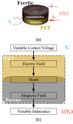
Fig. 1. (a) Schematic (b) Control mechanism of a voltage-controllable inductor
The voltage-controllable inductor (VCI) is one of the magnetoelectric components. Such de-vices help achieve efficient energy conversion with the coupling effect of electric and magnetic fields. By actively changing the inductance according to the feedback of the loads work condition, the VCI reduces the loss; thus, increasing the efficiency of power converters. The structure of the voltage-controllable inductor is shown in Fig. 1(a). It is comprised of two types of material: magnetostrictive material made from nick-zinc ferrite, and piezoelectric material made from lead zirconate titanate (PZT). For conventional inductors, there are only two terminals (a+ and a-), connecting with the circuit. With a VCI, there are two extra terminals (c+ and c-), connecting to a control voltage Vc, ranging from 0 V to 500 V. Fig. 1(b) shows the control mechanism. When a control voltage is applied to the control port, an electric field is generated in the inductor. This causes the piezoelectric layer to generate mechanical strain, compressing the magnetostrictive layer. With the strain, a magnetic field generated by the magnetoelectric effect, is superimposed on the original magnetic field. Thus, the in-ductance L(Vc) is controlled by the control voltage. To model the hysteresis and magnetoelectric effect of the VCI, the magnetic hysteresis loop under magnetoelectric effect is measured. The measurement method is introduced and explained for the modeling. Fig. 2 shows the experimental setup for the measurement. The modeling ap-proach and measurement error analysis are presented, based on the experimental results. Finally, this paper presents a model that considers the magnetic hysteresis and magnetoelectric effect for the voltage-controllable inductor. The new model shows good accuracy compared with the test results, as shown in Fig. 3. An equivalent SPICE model is provided for the inductor per-formance evaluation in the circuit level.
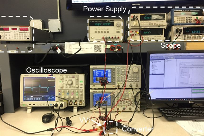
Fig. 2. Experimental setup for measuring hysteresis loop


