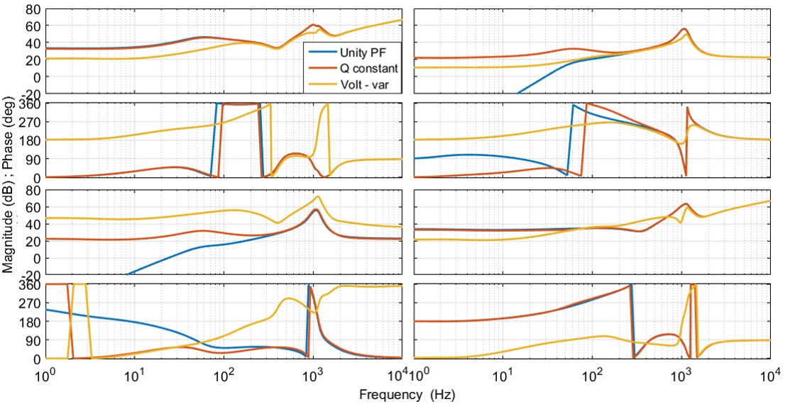
Fig. 1. PV impedances under mode 1 unity power factor, mode 2 constant Q, and mode 5 volt-var droop control
With the worldwide development of renewable energies, power systems are seeing higher prolif-eration at the distribution and transmission levels. SInce the negative incremental resistance caused by the constant-power behavior of power converters may cause stability problems, the stability of photovoltaic (PV) integration with the distribution system has begun to attract greater attention. Different from real-time simulations or the character root method, both of which require full models of all components in the distribution system, the generalized Nyquist stability criteri-on (GNC) for stability analysis of a three-phase AC power system uses only the measured D-Q frame impedances. Compared to the positive sequence impedance method, the D-Q frame im-pedance matrix method is more accurate for stability assessment of a system with a PV inverter that has non-symmetrical control in the D-Q frame, including DC voltage-loop and phase-locked-loop (PLL) controls.The goal of this paper is to derive the D-Q frame impedances of utility-scale PV inverters under five reactive power modes. Section II describes the derivation process. Section III offers a comparison of different Q control modes. Section IV shows the GNC application result based on impedances. Section V validates the impedance model using hardware experiments. Instability may occur when PV inverters are under reactive-power control mode of the volt-var (reactive power is a droop function of AC voltage), as a result of interactions amongof the voltage control of multiple PV inverters in parallel. The terminal impedances in DQ frame are derived of utility-scale PV farm based on small signal model of PV inverters. A comparison is done among impedances of PV inverters under 5 differ-ent reactive power control modes, based on which GNC is used to assess the grid-PV connec-tion stability. The volt-var control mode changes PV terminal impedance signs and magnitudes significantly and may cause unstable connection to the grid. The stability assessment is proved by time domain simulation and the derived impedances are validated by scaled-down hardware experiments.
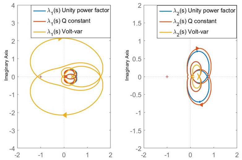
Fig. 2. Chatacteristid loci of PV connection to the grid.


