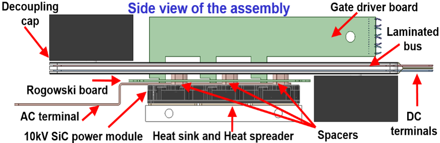
Fig. 1. Side view of the 10 kV power MOSFET half-bridge power module based H-bridge converter assembly the 10 kV power MOSFET half-bridge power module based H-bridge converter assembly
The main parts of the PEBB analyzed in this paper are shown in Fig. 1. It contains two 10 kV MOSFET half-bridge power modules with a self-designed laminated bus, smart gate drivers, sensing boards, etc. The power module connects to the laminated bus via a spacer-hole struc-ture. There is a self-designed embedded Rogowski coil PCB between the module and the bus, which measures the current going in and out from the DC power terminals of the module. Gate driver boards go through the holes from the top surface of the bus, all the way down, to be connected to the driving terminals of the power module beneath. Focusing on the insulation design and assessment, two kinds of insulation issues exist in the assembly. For example, internal defects, in the adhesive layer of the laminated bus can introduce excessive partial discharge internally, and thus significantly decrease the lifetime of the material around it. Meanwhile, the high electric stress on the exposed metal surfaces of the interconnectors, may cause partial breakdown of air and generate significant surface discharge. These two kinds of issues are demonstrated, as shown by Fig. 2. For the internal discharge issue, the insulation of a real laminated bus is evaluated. Some representative coupons are tested to demonstrate possible design issues for the existing bus and provide clues for further improvement. For the surface discharge issue along the inter-connectors, a three-dimensional electric field model, taking into account different switching status, is developed, and results of electric field intensity distributions are analyzed. Geometry-based modifications are then proposed to relieve the electric stress on the critical regions. The insulation performance of one type of interconnector mentioned in this paper, is tested and veri-fied. Afterwards, three kinds of surface treatment are individually applied on the exposed metal surface of the connector. The evaluation of the original structure, together with the comparison after applying different surface treatment material, is shown. A summary and some design guidelines are given at the end of the paper.
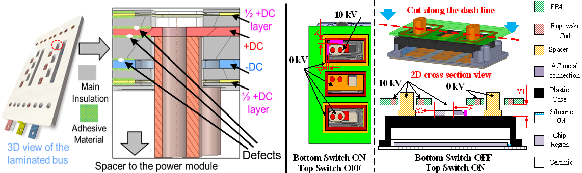
Fig. 2. Examples of internal and surfaces insulation issues inside the PEBB 6000 assembly


