


LIBRARY
High-Efficiency High-Density DC/DC Converter for Battery Charger Applications
Year: 2020 | Author: Feng Jin | Paper: P2.3

Fig. 1. Topology of proposed dc-dc converter.
and the easiest way to increase it is to cram more storage capacity into a vehicle. The long charging period with EVs own on-board- charger (OBC) makes EVs incomparable with traditional cars. A fast charging technique is the most promising method to a short charging period. In Teslas supercharger station, a Model X P100D can be fully charged within 75 minutes based on its 135 kW charging capacity. Porsche, a German high-performance sports car manufacturer, developed a 350 kW dc fast-charger for its 800 V battery pack of Taycan. Electric vehicle infrastructures, such as ChargePoint, Electrify America, etc., have staked their investment on 350 kW or higher power fast-charging stations. Considering different battery voltage ranges in state-of-the-art EVs, it is worthwhile for investors developing a battery charger with a wide output voltage range from 250 V to 800 V (or higher) to serve all mainstream EVs.
A modular approach is widely used in designing high power converters. In this paper, a bi-directional, isolated dc-dc converter with 850 V input voltage and 250-800 V output voltage is presented. By utilizing the three-phase interleaved CLLC resonant converter as the dc-dc stage, the charging power for one module is pushed to 12.5 kW. It can operate bi-directionally and achieve soft-switching with proper control. As a result, the switching frequency is pushed to 500 kHz to help reduce the converter size and weight. With the help of high-frequency operation, the transformers and inductors can be integrated together and built with PCB winding. Therefore, the proposed dc-dc converter will not only have very high density, but will also be very suitable for manufacturing automation. In order to achieve a wide output voltage range for battery charger applications to cover both state-of-the-art 400 V battery packs and 800 V battery packs in the near future, an interleaved buck converter with coupled inductors is adopted. Fig. 1 shows the topology structure of the proposed dc-dc module.
Fig. 2 shows the prototype picture of the proposed dc-dc module. The three phase transformers of the CLLC converter are inte- grated together and built with PCB winding. The coupled inductors of the buck converter use negative coupling to reduce switching frequency range and are also built with PCB winding. This module uses IMZ120R045M1 for both primary and secondary switches in the CLLC converter and C3M0075120J for switches in interleaving buck converters. The prototype has > 6 kW/L power density, in- cluding the heatsink. The detailed experimental results are provided in the full paper.
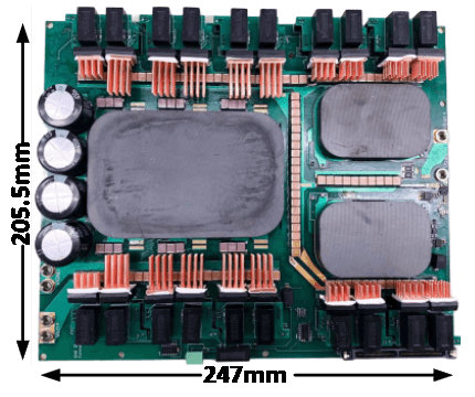
Fig. 2. Prototype picture.
