


LIBRARY
Current Sharing Behavior and Characterization of a 1200 V, 6.5 m&Omega SiC Half-Bridge Power Module with Flexible PCB Gate Loop Connection
Year: 2020 | Author: Grace Watt | Paper: T1.19
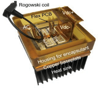
Fig. 1. Fabricated half-bridge power module with flexible PCB die interconnection and Rogowski coil for current sharing measurement
Novel packaging techniques include use of the flexible PCB as the gate-source connection, reducing the gate-loop inductance and decoupling the gate and source loops using a Kelvin source connection. Furthermore, the DBC is patterned with symmetrical current pathways for both switches, thereby mitigating possible differences in the power loops. Therefore, all the variation in switching behavior can be attributed to the differences in the selected dies.
Two power modules are designed to test current sharing behavior; the balanced module consists of carefully selected dies with matched threshold voltages (dies turn on at the same time), while the imbalanced module has dies with mismatched threshold voltages.Static and dynamic characterization demonstrate efficacy of the tech- niques utilized for this power module. Continuous testing in a boost converter demonstrates thermal performance of the modules.
An initial clamped inductive DPT allows for observation of the static and dynamic current sharing of the paralleled die in the balanced module. Static results suggest that the current increases unequally over time for the two die, most likely due to mismatched on-state resistances. Dynamic results confirm that the dies are turning on at the same time because they were selected with similar threshold voltages. The rates of increase and overshoot during turn-on are matched, which is desirable for reliable performance over time. In the imbalanced module, turn-on increased the loss of one die over the other (-16.4%), but turn-off increased the loss of the second (+8.95%) so that the overall difference (-4.32%) was not significant. The worst case of imbalance in threshold voltage (17.8%) resulted in doubling of total loss (2.52% to 4.32%). The overall loss difference indicates a small impact on the cooling system performance due to switching imbalance.
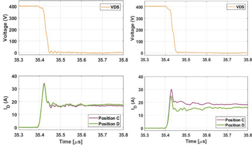
Fig. 2. Balanced and unbalanced dynamic current sharing comparison in a boost converter
